An366 – Cirrus Logic AN366 User Manual
Page 7
AN366
AN366REV2
7
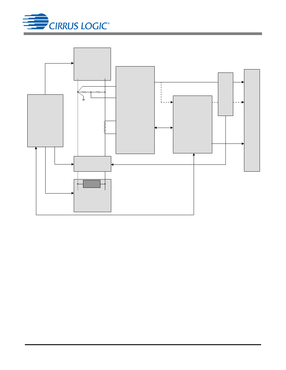
Figure 4 illustrates a typical hardware configuration for calibration and compensation:
Figure 4. Calibration and Compensation Hardware Configuration
Automation can be established by a calibration controller that starts the calibration and/or the compensation,
performs the required calculations, and finally initiates the storage of results. A calibration controller will control
the AC source and load during calibration by adjusting the load for different AFE input conditions. The controller
will also monitor the precision reference meter to confirm that load adjustments have been successfully execut-
ed, and the optical accumulation results are accurate from the Cirrus AFE. Communication from the controller
to the Cirrus AFE is processed through the meter application processor to the calibration controller. Calculations
and NVM results stored within the application processor are initiated by the controller when the calibration is
completed.
AC
LOAD
AC
SOURCE
CS5480 /84/90
(AFE)
L
N
VIN -
VIN +
IIN +
IIN -
Application
Processor
LOAD
CT
Pulse
Pulse
OR
Di
s
pl
ay
Power
Serial
Port
Reference
Meter
Op
ti
ca
l
Se
ns
o
r
Calibration
Controller