1 normal operation flow diagram using the cdb5484, An366 – Cirrus Logic AN366 User Manual
Page 20
AN366
20
AN366REV2
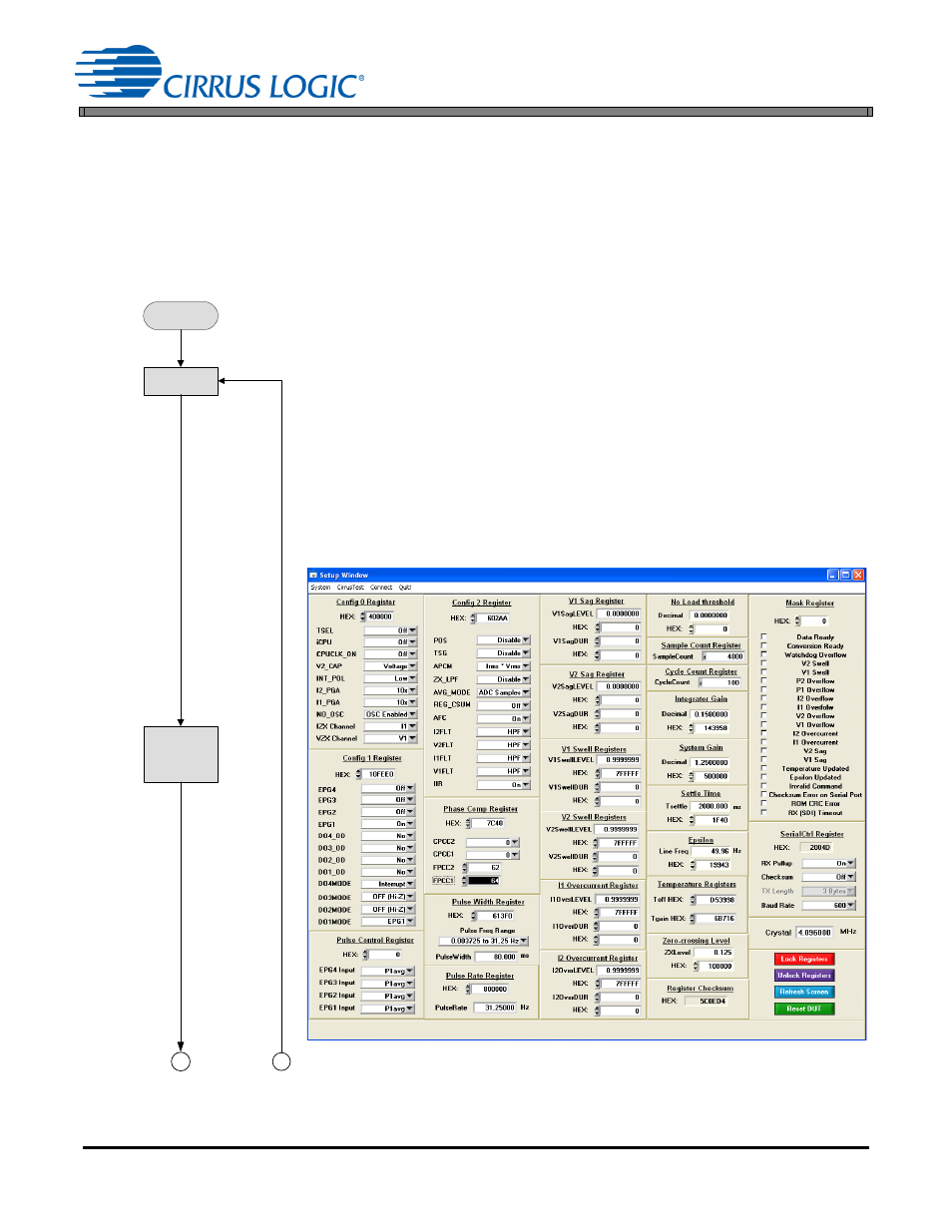
6.1 Normal Operation Flow Diagram Using the CDB5484
The following flow diagram shows the implementation of normal flow executed in the field. The CDB5484U is
used to load calibration constants obtained during the factory calibration. Obviously, the GUI is not used during
actual execution, but it provides an excellent debugger for customer flow evaluation and modifications. The one-
time factory calibration and compensation flows are discussed after the normal flow. The MTE Meter Test Equip-
ment source is used to provide the source voltage and load current, but it is only required during this flow to
simulate different loading conditions. Each step of the flow shows the CDB5484U GUI screen capture of execu-
tion and reading results. The register writes and reads are all identified for easy comparison to the GUI screen.
POWER UP
Power up CDB5484U per data sheet using terminals J36 and J37.
RESET
SDI = 0xC1
Reset CS5484 software Reset
RESTORE FILTER CONFIGURATION
(See Figure 14.)
Config 2 Register
SDI = 0x90
0x40 0x0602AA
Write Register Config2 to enable HPFs
SDO = 0xFF
0xFF 0xFFFFFF
(Page 16, Register 0)
SDI = 0x90
0x00 0xFFFFFF
Read Register Config2 to enable HPFs
SDO = 0xFF
0xFF 0x0602AA
(Page 16, Register 0)
Figure 14. Setup Window
POWER UP
From NVM
RESTORE
FILTER
CONFIGURATION
RESET
2
1