2 system scale example, An366 – Cirrus Logic AN366 User Manual
Page 3
AN366
AN366REV2
3
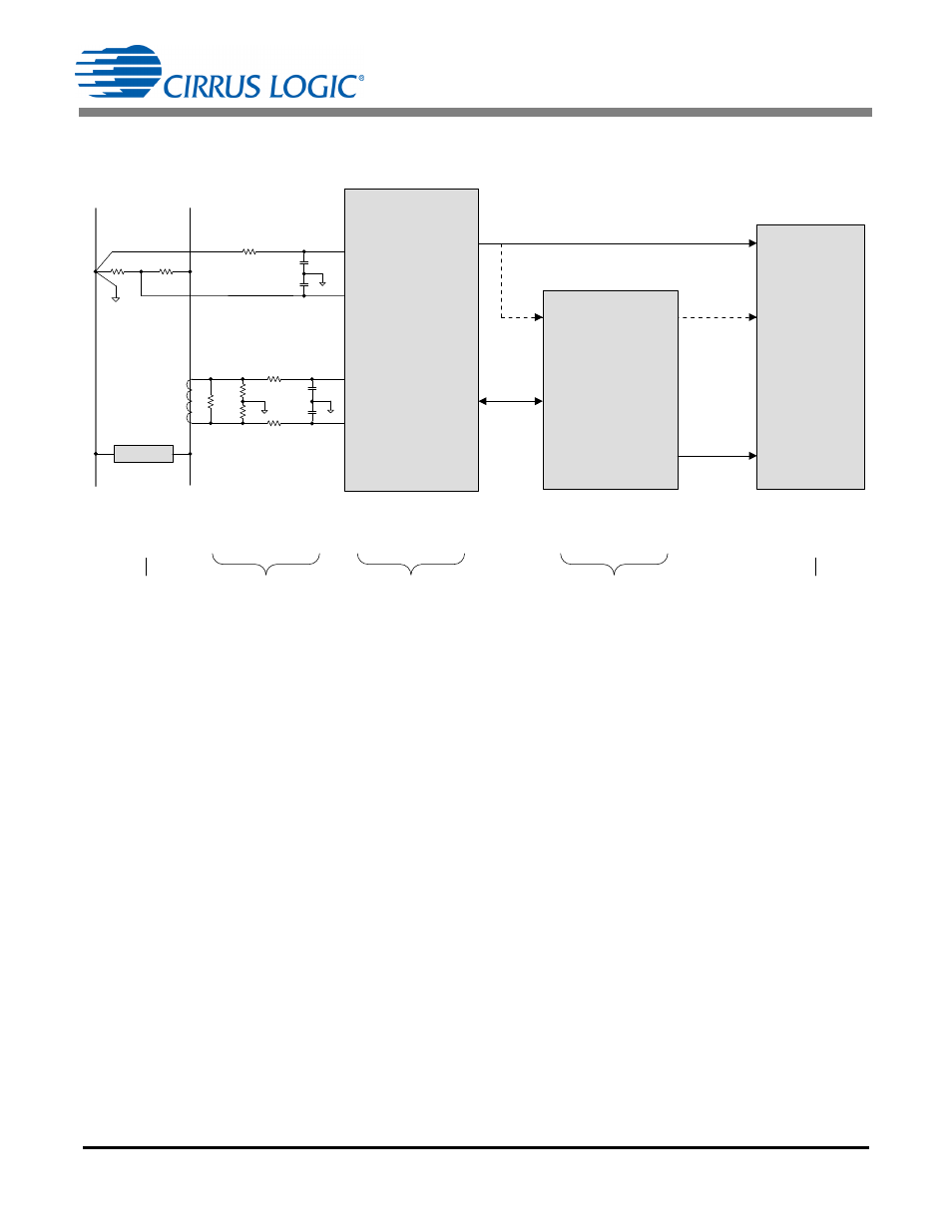
3.2 System Scale Example
Figure 1 illustrates an example of the system scaling.
Figure 1. System Scaling
-
Hardware Scale: The CS5480/84/90 inputs are scaled using attenuation circuits that apply a maximum
input amplitude of 176mV
RMS
or 35mV
RMS
, which is dependent on an AFE gain setting of 10x gain or
50x gain, respectively.
-
AFE Scale: The AFE registers record input levels that are displayed as a ratio of the most recent
measurement to the maximum RMS voltage and RMS current. The maximum RMS register value is
generated using a 0.6 ratio. The register value is read as a 24-bit hexadecimal number, which is
proportioned to represent a 0.6V
RMS
full scale. At maximum voltage (0.6) and maximum current (0.6)
the maximum power is P
MAX
= V
RMSMAX
× I
RMSMAX
= 0.6 × 0.6 = 0.36.
-
MCU Scale: The MCU is required to read all registers and interpret the 24-bit hexadecimal numbers
based on full-load conditions. Knowing the maximum hardware scaling and the most recent AFE
register values in relation to the full-scale input, the MCU routines are able to calculate the actual power
measurements.
CS5480 /84 /90
(AFE)
L
N
VIN-
VIN+
IIN+
IIN-
Application
Processor
LOAD
CT
Pulse
Pulse
OR
Display
Power
19.2kW
240 V
RMS
,
80A
RMS
176mV
RMS
,
35mV
RMS
19.2kW
240 V
RMS
,
80A
RMS
Pavg: ±0.36
V
RMS
: 0.6
I
RMS
: 0.6
Hardware
Scale
AFE
Scale
MCU
Scale
19.2kW
240 V
RMS
,
80A
RMS
Input
Output
Serial
Port