Input module for electrical/temperature signals, Output module for electrical/temperature signals – WIKA Pascal ET User Manual
Page 18
6 Commissioning, operation
18 WIKA Operating Instruction, Pascal ET and Pascal ET/IS
GB
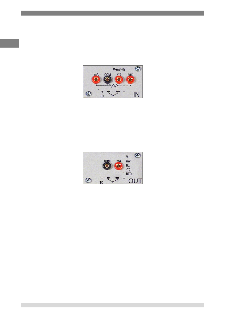
6.1.2.1 Input module for electrical/temperature signals
The input module for electrical/temperature parameters measurement is one of those modules
inserted from the instrument’s front panel; two slides drive the module into its position. It is possible
to have up to two input modules in the same instrument: IN A and IN B. This terminology is used
also by the software to carry out the connection between physical input IN and software channel.
For example: if you connect a thermoresistance Pt100 to module IN A, the temperature measured
by this thermoresistance can be displayed in any of the four software channels available. The
following figure shows the pins connection in electrical/temperature IN module.
Figure 1
– Input panel module
6.1.2.2 Output module for electrical/temperature signals
The output module for electrical/temperature parameters generation or simulation is one of those
inserted from the instrument’s front panel; two slides drive the module into its position. It is possible
to have up to two output modules in the same instrument: OUT A and OUT B. This terminology is
used also by the software to carry out the connection between physical output OUT and software
channel. For example: if you connect a signal-receiver to module output OUT A, the current
4…20
mA generated can be displayed in any of the four software channels available.
The following figure shows the output module for electrical/temperature parameters.
Figure 2
– Output panel module
The 2 INPUT cards and 2 OUTPUT cards are plug and play modules and can be installed by the
user himself.