6 connecting to the vp-81ksi via the rs-485 port, Connecting to the vp-81ksi via the rs-485 port, Figure 8: rs-485 dip-switches – Kramer Electronics VP-81KSi User Manual
Page 17: Table 3: rs-485 dip-switch settings, N 6.6.1, N 6.6
Connecting the VP-81KSi 8x1 UXGA/Audio STEP-IN Switcher
13
6.6 Connecting to the VP-81KSi via the RS-485 Port
You can operate the VP-81KSi via the RS-485 port from a distance of up to
1200m (3900ft) using any device equipped with an RS-485 port (for example, a
PC). For successful communication, you must set the RS-485 machine number and
bus termination.
To connect a device with a RS-485 port to the VP-81KSi:
•
Connect the A (+) pin on the RS-485 port of the PC to the A (+) pin on the
RS-485 port on the rear panel of the VP-81KSi
•
Connect the B (–) pin on the RS-485 port of the PC to the B (–) pin on the
RS-485 port on the rear panel of the VP-81KSi
•
Connect the G pin on the RS-485 port of the PC to the G pin on the RS-485
port on the rear panel of the VP-81KSi
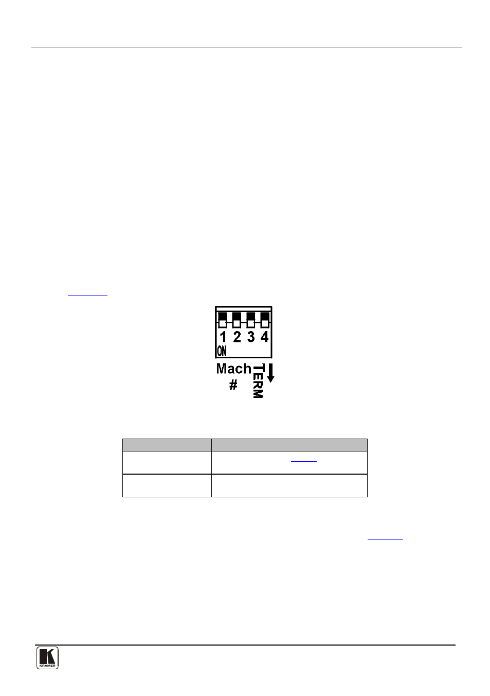
6.6.1 Setting the RS-485 Machine Number and Bus Termination DIP-switches
This section describes the VP-81KSi DIP-switch settings that determine the
RS-485 machine number and bus termination.
illustrates the factory default DIP-switch positions.
Figure 8: RS-485 DIP-switches
Table 3: RS-485 DIP-switch Settings
DIP-switch Number
Function
1, 2, 3
Machine number (see
Default—All off (up), machine number 1
4
RS-485 Bus Termination
Default—Off (up)
DIP-switches 1, 2 and 3 determine the RS-485 machine number of the
VP-81KSi. When several VP-81KSi units are connected, the machine number
determines the unique identity of the VP-81KSi on the bus (see
Note:
•
When using a stand-alone VP-81KSi unit, set the machine number to 1
(factory default)
•
When connecting more than one VP-81KSi, set the first machine (connected
via RS-232) to be machine number 1. The other VP-81KSi units must each be
set to a unique machine number between 2 and 16