Kramer Electronics VP-81KSi User Manual
Page 10
KRAMER: SIMPLE CREATIVE TECHNOLOGY
Defining the VP-81KSi 8x1 UXGA/Audio STEP-IN Switcher
6
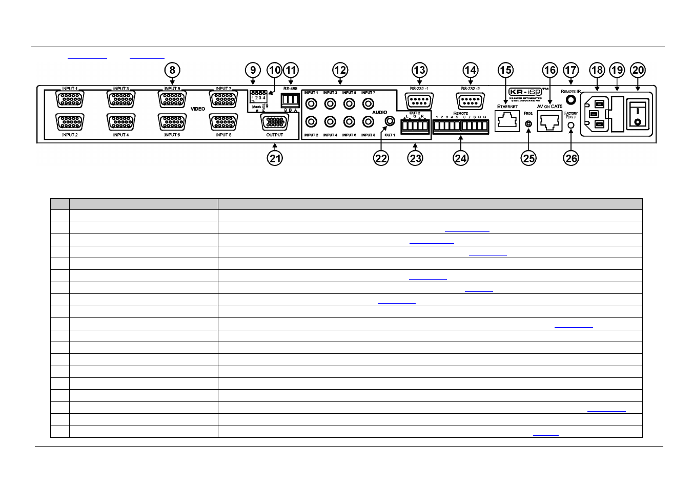
define the rear panel of the VP-81KSi 8x1 UXGA/Audio STEP-IN Switcher.
Figure 2: VP-81KSi 8x1 UXGA/Audio STEP-IN Switcher Rear Panel
Table 2: VP-81KSi 8x1 UXGA/Audio STEP-IN Switcher Rear Panel Features
#
Feature
Function
8
VIDEO INPUT 15-pin HD (F) Connectors Connect to the VGA (up to WUXGA) sources (from 1 to 8)
9
Mach # DIP-switches
DIP-switches 1, 2 and 3 assign the RS-485 machine number (see
Section 6.6.1
10
TERM DIP-switch
DIP-switch 4 sets the RS-485 termination on or off (see
Section 6.6.1
11
RS-485 Terminal Block
Connect to RS-485 port on a remote controller or another VP-81KSi (see
Section 6.6
12
AUDIO INPUT 3.5mm Mini Jacks
Connect to the unbalanced stereo audio sources (from 1 to 8)
13 RS-232-1 9-pin D-sub Port (F)
Connect to the RS-232 port on a remote controller (see
Section 6.3
14
RS-232-2 9-pin D-sub Port (M)
Connect to an RS-232 controllable device (for example, a projector, see
15 ETHERNET RJ-45 Connector
Connect to a remote controller via a LAN (see
Section 6.9
16
AV ON CAT 5 RJ-45 Connector
Connect to a compatible TP receiver (for example, TP-122)
17 REMOTE IR 3.5mm Mini Jack
Connect to an external IR receiver unit for controlling the machine via an IR remote controller (see
Section 4.1
18
Mains Power Connector
Connect to the AC mains supply
19 Main Power Fuse
Fuse for protecting the unit
20 Mains Power Switch
AC mains switch
21 OUTPUT 15-pin HD Connector
Connect to the VGA (up to WUXGA) acceptor
22 AUDIO OUT 1 3.5mm Mini Jack
Connect to the unbalanced stereo audio acceptor
23 AUDIO OUT 2 Terminal Block Connector Connect to the balanced stereo audio acceptor
24 REMOTE Switch Terminal Block
Connect to contact closure switches for duplicating the function of the front panel Input Selector buttons (see
Section 6.2
25
PROG. Button
For the use of Kramer technical support only
26 FACTORY RESET Button
Press and hold while turning the unit on to reset all parameters to factory default values (see