Festo Пассивные нправляющиеFDG-ZR-RF User Manual
Page 21
FDG−...−ZR−RF
Festo FDG−...−ZR−RF 0404NH English
21
If the FDG−...−ZR−RF is used in conjunction with a drive axis type DGE−... or
DGP(L)−...:
1. Make sure that the slide surfaces of both
axes lie at the same level within the comĆ
plete positioning stroke.
2. Position the FDG−...−ZR−RF exactly parallel
to the drive axis.
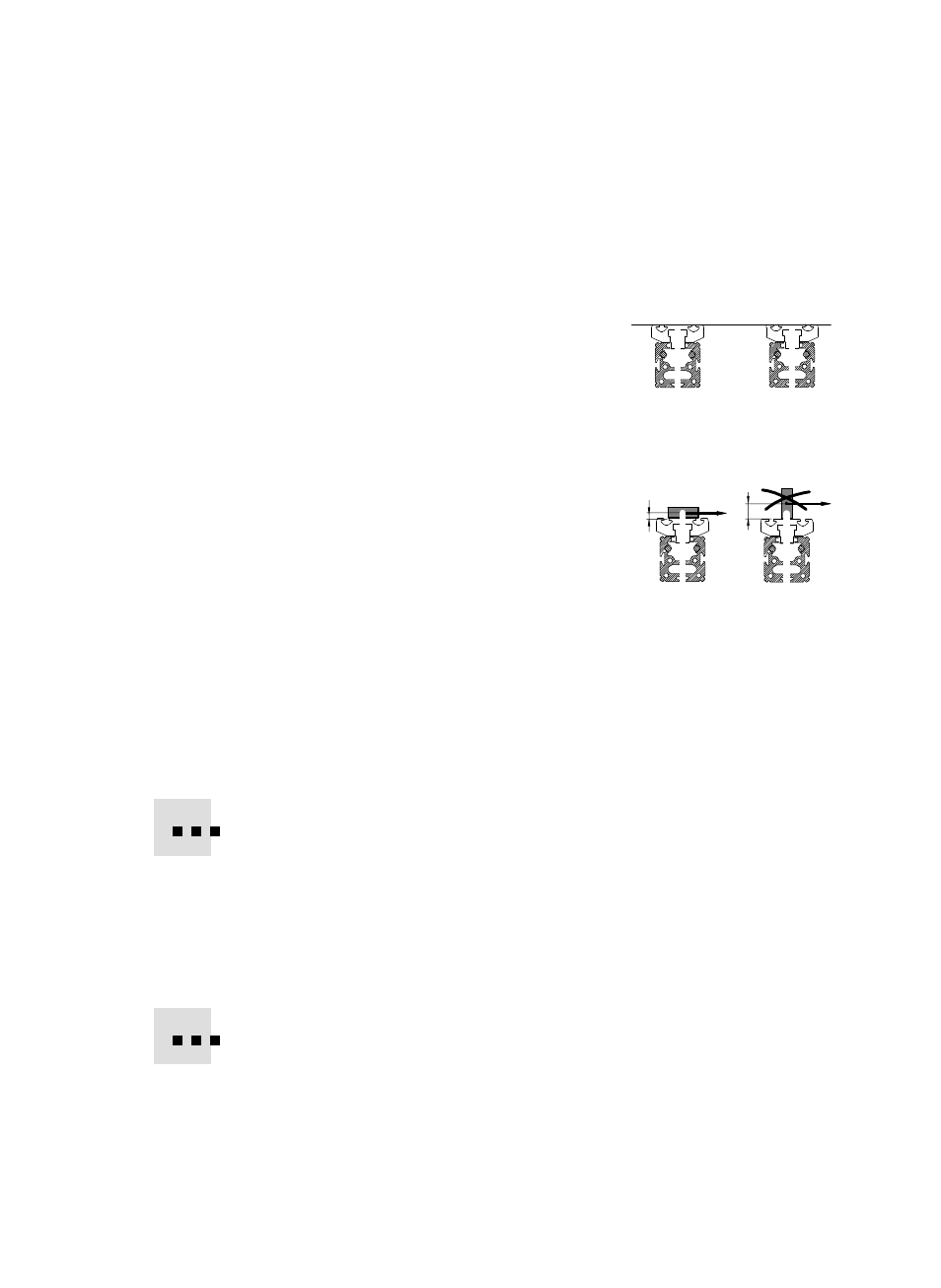
3. Place the bridge (see Fig. 2) and the work
load onto the slides of the FDG−...−ZR−RF and
the drive axis as follows:
ć The tilting torque of force F parallel to the
cylinder axis and distance d remains low.
Force F includes here the inertial force
F = m
⋅ a, the force due to weight and
possible external forces.
ć Only loadings within the framework of
the permitted values are effective
(seeĂTechnicalĂspecifications").
4. Push the bridge over the complete stroke path from one end position to the
other.
The guide axis will then position itself free of distortion to the drive axis.
5. Tighten the fastening screws (see Fig. 7: Q) of the guide axis.
Check whether shock absorbers or stops are also required externally.
Interrogating the slide positions
S
Use sensors with inductive switching in conjunction with ferritic switching
lugs.
S
Complete the fitting of the sensors in accordance with the operating instrucĆ
tions for the sensors and for the drive axis.
You can protect unused sensor grooves against dirt deposits at best with cover
rails as described in the chapter Accessories".
Fig. 9
Fig. 10
F
F
d
d