Tie-rod torque specifications and procedure – Goulds Pumps 3393 - IOM User Manual
Page 120
Appendix
Forces (lbf)
Moments (ft-lbs)
Vertical
2.5
200
165
250
360
520
260
395
705
nozzle
4
320
260
400
570
980
500
740
1330
perpen-
5
440
360
550
790
1340
685
1020
1820
dicular to
the shaft 6
560
460
700
1010
1700
870
1300
2310
(ES and
RS)
Hoizon-
2.5
200
165
250
360
520
260
395
705
tall noz-
4
320
400
260
570
980
500
740
1330
zle per-
5
440
550
360
790
1340
685
1020
1820
pendicu-
lar to the 6
560
700
460
1010
1700
870
1300
2310
shaft (ES
and RS)
Table 12: Discharge Nozzle Configuration (Metric units)
Forces (N)
Moments (Nm)
Flange
Fx
Fy
Fz
Σ F
Mx
My
Mz
Σ M
Size (in)
Vertical
2.5
890
734
1112
1601
705
352
535
955
nozzle
4
1423
1156
1779
2535
1328
678
1003
1802
perpen-
5
1957
1601
2446
3514
1816
928
1382
2466
dicular to
the shaft 6
2491
2046
3114
4492
2304
1179
1762
3130
(ES and
RS)
Hoizontal 2.5
890
734
1112
1601
705
352
535
955
nozzle
4
1423
1779
1156
2535
1328
678
1003
1802
perpen-
5
1957
2446
1601
3514
1816
928
1382
2466
dicular to
the shaft 6
2491
3114
2046
4492
2304
1179
1762
3130
(ES and
RS)
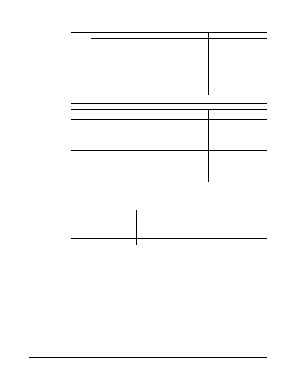
Tie-Rod Torque Specifications and Procedure
Appendix D
Model
Size (mm)
English units
Metric units
50% ft-lb
100% ft-lb
50% N-m
100% N-m
2.5x4-8 (65)
20x2.5
N/A
163
N/A
221
4x5-10 (100)
24x3
140
281
191
381
5x6-11 (125)
30x3.5
280
559
379
758
6x8-13 (150)
36x4
488
976
662
1324
Mark casings as shown below and apply torque values in this sequence or as noted in the
instructions below.
118
Model 3393 Installation, Operation, and Maintenance Manual