Maximum allowable forces and moments – Goulds Pumps 3393 - IOM User Manual
Page 119
Appendix
English Units (inches)
Metric Units (mm)
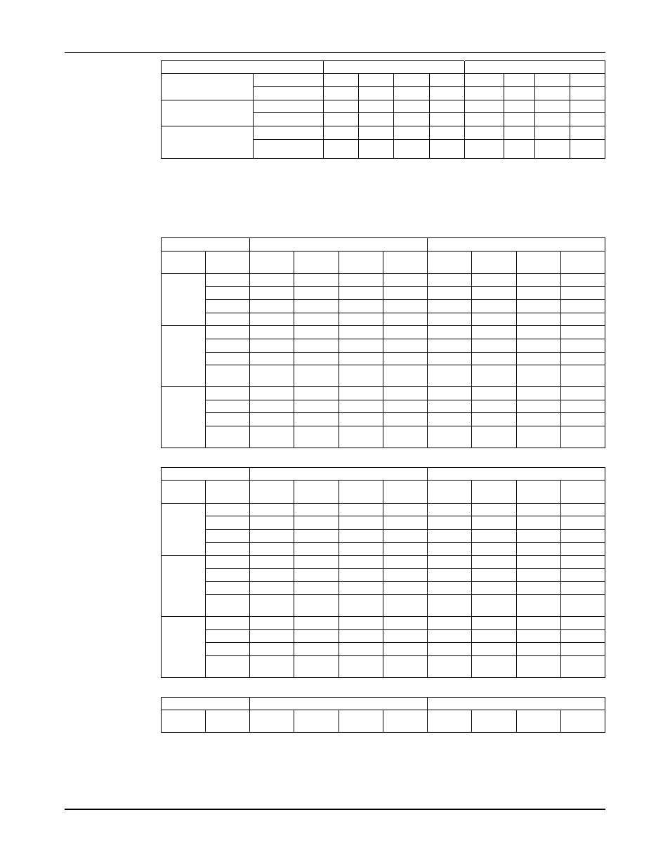
Impeller Hub to Dif-
Normal
0.020
0.020
0.020
0.020
0.50
0.50
0.50
0.50
fuser
Replace
0.040
0.040
0.040
0.040
1.00
1.00
1.00
1.00
Balance Drum to
Normal
0.016
0.016
0.016
0.016
0.40
0.40
0.40
0.40
Stator
Replace
0.032
0.032
0.032
0.032
0.80
0.80
0.80
0.80
Suction Bearing
Normal
0.004
0.004
0.004
0.004
0.10
0.10
0.10
0.10
Bushing to Sleeve
Replace
0.008
0.008
0.008
0.008
0.20
0.20
0.20
0.20
(ES)
Maximum allowable forces and moments
Appendix C
Table 9: Suction Nozzle Configuration (English units)
Forces (lbf)
Moments (ft-lbs)
Flange
Fx
Fy
Fz
Σ F
Mx
My
Mz
Σ M
Size (in)
Horizon- 5
550
440
360
790
1340
685
1020
1820
tal nozzle 6
700
560
460
1010
1700
870
1300
2310
parallel to
8
1100
850
700
1560
2600
1300
1900
3500
the shaft
(ES)
10
1500
1200
1000
2200
3700
1800
2800
5000
Vertical
4
320
260
400
570
980
500
740
1330
nozzle
5
440
360
550
790
1340
685
1020
1820
perpen-
6
560
460
700
1010
1700
870
1300
2310
dicular to
the shaft 8
850
700
1100
1560
2600
1300
1900
3500
(RS)
Horizon- 4
320
400
260
570
980
500
740
1330
tal nozzle 5
550
440
360
790
1340
685
1020
1820
perpen-
6
560
700
460
1010
1700
870
1300
2310
dicular to
the shaft 8
850
1100
700
1560
2600
1300
1900
3500
(RS)
Table 10: Suction Nozzle Configuration (Metric units)
Forces (N)
Moments (Nm)
Flange
Fx
Fy
Fz
Σ F
Mx
My
Mz
Σ M
Size (in)
Horizon- 5
2446
1957
1601
35140
1816
928
1382
2466
tal nozzle 6
3114
2491
2046
4492
2304
1179
1762
3130
parallel to
8
4893
3781
3114
6939
3523
1762
2575
4743
the shaft
(ES)
10
6672
5338
4448
9786
5014
2439
3794
6775
Vertical
4
1423
1156
1779
2535
1328
678
1003
1802
nozzle
5
1957
1601
2446
3514
1816
928
1382
2466
perpen-
6
2491
2046
3114
4492
2304
1179
1762
3130
dicular to
the shaft 8
3781
3114
4893
6939
3523
1762
2575
4743
(RS)
Horizon- 4
1423
1779
1156
2535
1328
678
1003
1802
tal nozzle 5
2446
1957
1601
3514
1816
928
1382
2466
perpen-
6
2491
3114
2046
4492
2304
1179
1762
3130
dicular to
the shaft 8
3781
4893
3114
6939
3523
1762
2575
4743
(RS)
Table 11: Discharge Nozzle Configuration (English units)
Forces (lbf)
Moments (ft-lbs)
Flange
Fx
Fy
Fz
Σ F
Mx
My
Mz
Σ M
Size (in)
Model 3393 Installation, Operation, and Maintenance Manual
117