Seal-chamber cover removal – Goulds Pumps 3196 i-FRAME - IOM User Manual
Page 73
Maintenance
6. To loosen the impeller, quickly turn the impeller counter-clockwise (viewed from the
impeller end of the shaft) while impacting the wrench handle on the workbench or a solid
block.
7. Repeat step 6 until the impeller becomes loose.
8. If step 6 and 7 do not work then do this:
a) Place a socket wrench over the cast nut on the impeller hub.
b) Turn the impeller counter-clockwise (viewed from the impeller end of the shaft).
Be sure that the impeller wrench rests on the workbench or a solid block and that the power
end is secure on the work surface.
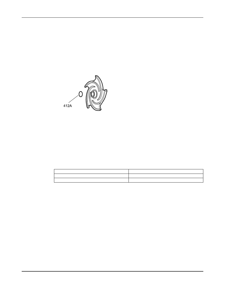
9. Remove and discard the impeller O-ring (412A).
You will insert a new O-ring during reassembly.
Figure 17: O-ring for models 3196 and HT 3196
If the impeller cannot be removed by the previous methods, cut the shaft between the gland
and the frame, remove the impeller, stuffing-box cover, gland, sleeve, and shaft end as a unit.
Do not apply heat.
Seal-chamber cover removal
Seal-chamber removal procedures
Choose from one of these procedures to remove the seal-chamber cover.
Table 10: Procedures for seal-chamber cover removal by model
Model
Procedure
3196, CV 3196, HT 3196, LF 3196, 3796
Remove the seal-chamber cover.
NM 3196, 3198
Remove the seal-chamber cover and/or backplate.
Remove the seal-chamber cover (3196, CV 3196, HT 3196, LF 3196, 3796)
1. Remove the gland stud nuts (355).
2. Remove the seal-chamber stud nuts (370H).
Model 3196 i-FRAME Installation, Operation, and Maintenance Manual
71