Pump-to-driver alignment instructions – Goulds Pumps 3196 i-FRAME - IOM User Manual
Page 32
Installation
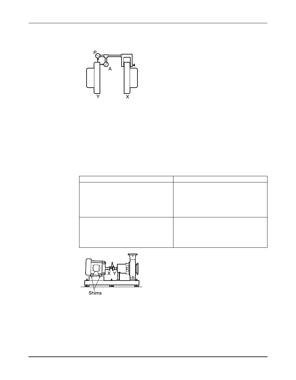
b) Attach the other indicator (A) so that the indicator rod comes into contact with the inner
end of the driver coupling half.
This indicator is used to measure angular misalignment.
2. Rotate the pump coupling half (X) in order to check that the indicators are in contact with
the driver coupling half (Y) but do not bottom out.
3. Adjust the indicators if necessary.
Pump-to-driver alignment instructions
Perform angular alignment for a vertical correction
1. Set the angular alignment indicator to zero at the top-center position (12 o’clock) of the
driver coupling half (Y).
2. Rotate the indicator to the bottom-center position (6 o’clock).
3. Record the indicator reading.
When the reading value is...
Then...
Negative
The coupling halves are farther apart at the
bottom than at the top. Perform one of these
steps:
• Add shims in order to raise the feet of the
driver at the shaft end.
• Remove shims in order to lower the feet of
the driver at the other end.
Positive
The coupling halves are closer at the bottom
than at the top. Perform one of these steps:
• Remove shims in order to lower the feet of
the driver at the shaft end.
• Add shims in order to raise the feet of the
driver at the other end.
Figure 11: Side view of an incorrect vertical alignment
4. Repeat the previous steps until the permitted reading value is achieved.
Perform angular alignment for a horizontal correction
1. Set the angular alignment indicator (A) to zero on left side of the driver coupling half (Y),
90° from the top-center position (9 o’clock).
2. Rotate the indicator through the top-center position to the right side, 180° from the start
position (3 o’clock).
30
Model 3196 i-FRAME Installation, Operation, and Maintenance Manual