Myron L Aquaswitch II User Manual
Page 41
3. SENSOR SUBSTITUTE CALIBRATION
NIST traceable Sensor Substitutes are commonly use to verify
and calibrate Resistivity Monitor/controllers. Normally they are
not needed due to the “built-in “ electronic calibration or “Full
Scale Test”. However, your requirements may be such that a
crosscheck or verification is required. Sensor Substitutes are
available from the Myron L Company, see accompanying chart,
figure V.D.1, for part number.
If the proper Resistivity Sensor Substitute is not readily available
and you can not wait for one to be delivered, one may be
constructed using the equivalent resister values listed on the
accompanying chart, figure V.D.1 and schematic, figure V.D.2.
NOTE: If you have previously performed a system calibration
with either a NIST Standard Solution, or using the transfer
standard method, using this procedure will make that calibration
invalid. You must decide which is more important, a system
calibration, or an electronic calibration.
1.
Ensure power is OFF.
2.
Using a standard slot screwdriver remove the two (2)
screws on the front panel.
3.
Carefully wiggle the front panel and pull gently toward
you. Do not pull more than about 8 inches/20CM or you
could damage the wiring harness.
4.
Turn the front panel around so that the back side is
facing you and set aside.
5.
Locate and remove the sensor leads from the sensor
connector as shown in figure V.A.3.
6.
Install Sensor Substitute with label toward transformer
as shown in figure V.D.3.
7.
Turn power ON.
8.
Display reading should be full scale of range. If not,
adjust CALibration control to read full scale, i.e. 0-50 K
Ω
range should indicate 50, 0-10.00 M
Ω
= 10.00, and 0-
20.00 M
Ω
= 20.00 at full scale.
9.
After adjustment, turn power OFF.
10. Re-install front panel as described below in
“REASSEMBLY”.
11. To operate, turn power ON.
4. TRANSFER STANDARD METHOD
For maximum accuracy of any
AQUASWITCH II
Monitor/controllers, the transfer standard method should be
utilized. Instead of removing the entire Monitor/controller and
sensor, and either returning it to the manufacture or sending it to
a third party laboratory for recertification, the transfer standard
allows quick recertification and return to service — less down
time. While being the most accurate method it is also very easy to
perform, and may be used to calibrate ANY manufacture
Monitor/controller — resistivity or conductivity/TDS. This method
still has the benefit of third party verification, if so desired.
1.
A high quality hand-held instrument, one capable of
accurate conductivity/TDS and/or “resistivity” readings
such as the Myron L Ultrameter™, is calibrated using a
standard solution, or if so desired, sent to a third party
laboratory for calibration & certification. Preferably the
standard solution should be as close as practicable to
38
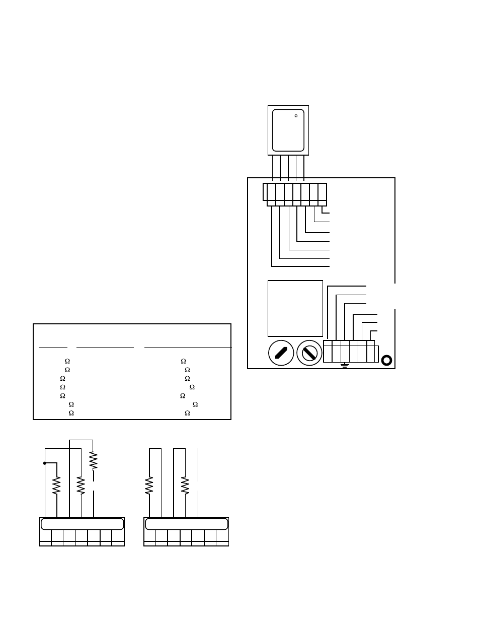
Figure V.D.3
ELECTRICAL CONNECT DIAGRAM
CHASSIS GROUND for
OEM INSTALLATIONS ONLY
SENSOR
L N
0-10VDC
OUTPUT
NEU
GRN
RED
WHT
BLK
(+)
(-)
ALARM
CONTROL
RELAY
NC
NO
COM
MAIN
INPUT
POWER
}
}
FUSE
1 1 5 / 2 3 0
SWITCH
LINE-BLK/+DC
NEU-WHT/-DC
GND-GRN
SENSOR
SUBSTITUTE
LABEL
CS-11
20 MEG
RESISTIVITY
SENSOR
SUBSTITUTE
NIST TRACEABLE
INSTALL WITH
LABEL TOWARD
TRANSFORMER
MYRON L
COMPANY
5-01
SENSOR SUBSTITUTE
LABEL TOWARD
TRANSFORMER
}
}
TRANSFORMER
RESISTIVITY MONITOR/CONTROLLER
RANGE
PART NUMBER
RESISTER VALUE - X*
0-20 M
C S - 1 1
1 M
0-10 M
C S - 1 2
50 K
0-5 M
C S - 1 3
20 K
0-2 M
C S - 1 4
100 K
0-1 M
C S - 1 5
5 K
0 - 5 0 0 K
C S - 1 6
2 4 . 9 K
0 - 2 0 0 K
C S - 1 7
10 K
* 1 %
Figure V.D.1
10K 1%
X
NC
CONDUCTIVITY/TDS
Figure V.D.2
5.49K 1%
100K 1%
X
R E S I S T I V I T Y
BK WT RD GN NU R- R+
BK WT RD GN NU R- R+