Myron L Aquaswitch II User Manual
Page 19
6. SOLENOID VALVE CONNECTIONS
The solenoid valves require electrical power to operate. This
power must be supplied by the user. See figure II.E.10 for the
suggested valve wiring. This section provides the procedures for
making the appropriate electrical connections.
a. External Power Connection
Valves powered by an external USER supplied source, i.e.
115/230 or 24 VAC.
1.
Place the USER supplied power cable and watertight
cable restraint into the enclosure’s appropriate access
hole.
2.
Connect the cable wires to the Power Board terminal
block as shown in figure II.E.1 or II.E.2.
For 24 VAC applications, the Myron L Company offers a 115 VAC
to 24 VAC transformer, Model #VR. Other voltages must be user-
supplied.
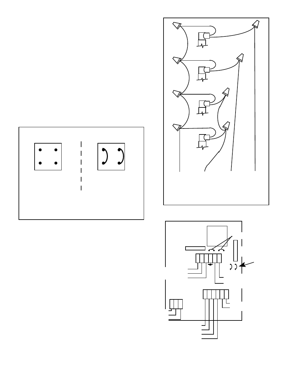
b. Valve Wiring
Suggested method of wiring solenoid valves. See figure II.E.10.
1.
Place the Bank A Valve solenoid interface cable and
watertight cable restraint into the enclosure’s
appropriate access hole.
2.
Neatly connect the cable wires to Power Board terminal
block as shown in figure II.E.1 or II.E.2.
3.
Repeat steps 1 and 2 to install the Bank B Valve solenoid
interface cable.
4.
Repeat steps 1 and 2 to install the Bleed Valve solenoid
interface cable.
5.
(Optional) Repeat steps 1 and 2 to install the Process
valve solenoid interface cable.
REASSEMBLY
1.
Carefully reinstall the front panel, bottom first.
Ensure no wires have been pinched between
enclosure and front panel.
2.
Reinstall the two (2) screws and tighten.
3.
To operate, turn power ON.
16
VALVE
A
VALVE
B
BLEED
VALVE
OPTIONAL
PROCESS
VALVE
TO
BLEED
TO
BANK A
TO
BANK B
TO
COM
SUGGESTED VALVE WIRING
DIAGRAM
Figure II.E.10
Figure II.E.9
For jumper location, see Figure II.E.11.
AQUASWITCH
POWER BOARD
SOLENOID VALVE POWER JUMPER
DIAGRAM
CUSTOMER POWERED
SOLENOID OUTPUT
(STANDARD)
OPTIONAL
SELF-POWERED
SOLENOID OUTPUT
(ADD BUSS WIRE
JUMPERS AS SHOWN)
FOR EARLY MODELS
Figure II.E.11
EARLY MODEL
AQUASWITCH
ELECTRICAL CONNECTION DIAGRAM
AQUASWITCH™
POWER BOARD
TRANSFORMER
SOLENOID
VALVE
OUTPUT
POWER
BANK B
BANK A
BLEED
COM
MAIN
INPUT
POWER
LINE / +DC
(BLK)
NEUTRAL / -DC
(WHT)
NC
NO
COM
GRD
C
AC
ALARM
RELAY
NO
COM
NC
FUSE
1/8 Amp
AGC 1/8
WHT
BLK
SOLENOID
INPUT
POWER
LINE
NEUTRAL
BK B
BK A
BLD
COM
LOGIC
BOARD
CONNECTION
INPUT FROM
CONTROLLER
RELAY
115/230
JUMPERS
}
}
{
SOLENOID
VALVE
POWER
JUMPERS
{