Iii. options & accessories – Myron L Aquaswitch II User Manual
Page 23
III. OPTIONS &
ACCESSORIES
A .
4A/4AO MODULE (4-20mA OPTION)
-4A
4-20mA Self/Remote-powered Isolated output module
ordered with Monitor/controller.
4AO
4-20mA Self/Remote-powered Isolated output module
ordered separately (includes harness).
1 . D E S C R I P T I O N
The 4-20mA option gives the
AQUASWITCH II
Monitor/controller the ability to send a signal very long distances
with minimal interferences and signal degradation. The output is
an Isolated 4-20mA signal that corresponds to the full scale range
of the Monitor/controller into which it is installed. This output is
easily configured to be either self-powered or remote-powered as
required for your particular application.
NOTE: The maximum impedance of the user's current input
instrument should not exceed 600 ohms.
Since the output is an isolated current loop, it is the ideal choice
for applications requiring; a control signal to be run very long
distances, systems requiring a 4-20mA input or in instances
where isolation is necessary.
As the output is isolated, and a current, it is useful for long
distance interface, especially where wiring resistances may be
high, and/or the ground potentials may differ between the sensor
input ground and the current receiving instruments ground.
The 4-20mA output will not be degraded in accuracy even when
the ground differences are as much as 120VAC @ 60Hz.
Interface wire resistance of 350
Ω
will not degrade the accuracy of
the output when interfaced to a typical 250
Ω
input impedance of a
transmitter current input device.
The output is capable of driving a minimum of 600
Ω
worse case,
therefore, will satisfy virtually all modern interface requirements.
Current input devices usually have an input impedance of 250
Ω
,
however, some older designs can have as high as 500
Ω
or as low
as 10
Ω
. This “-4A” option will drive any impedance from 0 to 600
Ω
without any degradation of performance.
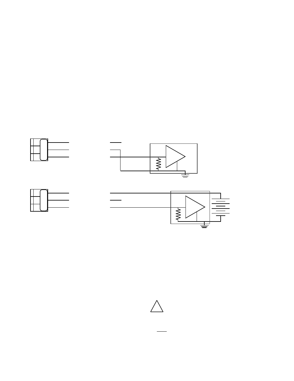
There are two modes in which current loop transmitters operate;
Self-Powered and Remote-Powered.
Self-Powered — the transmitter provides the power to drive
the 4 to 20 mA current. See figure III.A.1.
Remote-powered — the receiving instrument provides the
power to drive the 4 to 20 mA current. See figure III.A.2.
Specifications
Self-Powered and Remote-Powered
Drive Impedance — 0 to 600
Ω
Common Mode Maximum — 120VAC @ 60 Hz
Isolation — 100pf max. to Model 750II circuit common
100pf max. to input power line
Calibration
Two multi-turn pots — Factory Set.
4mA
=
Zero (0)
20mA
=
Full Scale
Calibration is NOT required. However, if you feel you must verify
or recalibrate, see Recalibration below.
2. INSTALLATION
Briefly -
The 4-20 Module replaces the plastic display retainer plate
attached to the front panel.
The 4-20 Module harness is attached to the main circuit board as
marked ‘4-20’. See figure III.A.4.
The 4-20 output is wired as required - Self-powered or Remote-
powered. See figures III.B.1 & III.A.2.
!
CAUTION - READ FOLLOWING CAREFULLY
WARNING: BEFORE STARTING, IF THE
AQUASWITCH
IS INSTALLED, ENSURE THE POWER
I S OFF. FAILURE TO DO SO COULD CAUSE DAMAGE
TO THE INSTRUMENT, AND COULD BE HARMFUL OR
FATAL TO PERSONNEL. ONLY QUALIFIED
PERSONNEL SHOULD INSTALL ELECTRICAL
E Q U I P M E N T .
20
Figure III.A.1
CURRENT INPUT INSTRUMENT
Self - Powered
(+)
(-)
+
-
(+)
SIGNAL OUT
POWER OUT
POWER IN
+
N
Figure III.A.2
CURRENT INPUT INSTRUMENT
Remote - Powered
(+)
(-)
+
-
(+)
SIGNAL OUT
POWER OUT
POWER IN
+
+ 35 VDC
MAXIMUM
N
4A (4-20mA) Wiring Options
SO PO PI
SO PO PI