Myron L Aquaswitch II User Manual
Page 39
B .
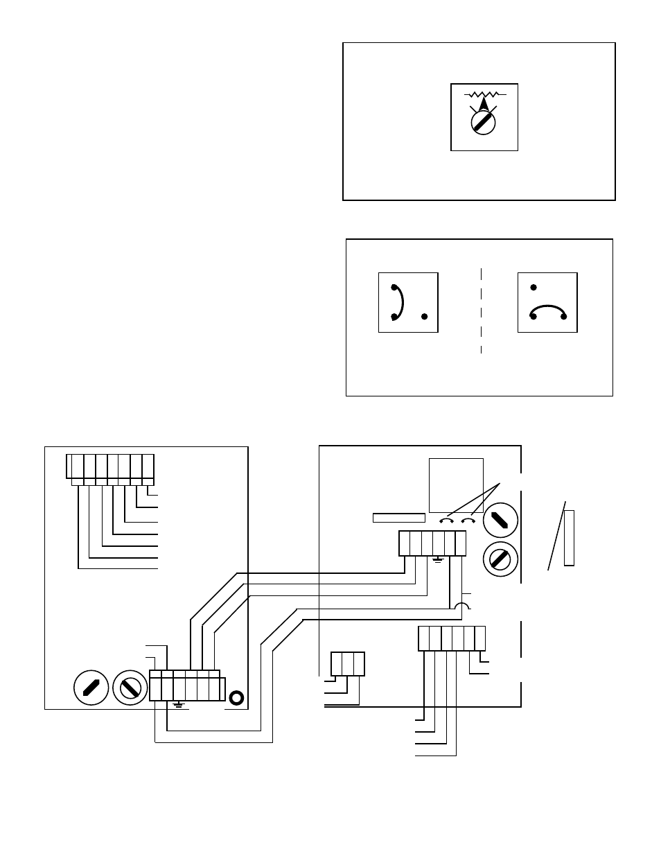
“PURGE CYCLE” CALIBRATION
PROCEDURE
The Purge Cycle control adjustment (see figure V.A.1) determines
the time span that the Bleed and Process solenoid valves are
energized during either a Bank A or B Purge Cycle.
Turning the adjustment screw fully clockwise equals a minimum
Purge Cycle of approximately one (1) minute. Turning the
adjustment screw fully counterclockwise equals a maximum
Purge Cycle of nine (9) to thirteen (13) minutes.
1.
Being careful not to excessively strain the cable(s),
unfasten the enclosure’s front panel.
2.
Turn the Logic Board adjustment to the desired Purge
Cycle setting. See figures V.A.1 and V.B.1.
C .
“ALARM RESET” MODE CHANGE PROCEDURE
The
AQUASWITCH I
and
AQUASWITCH II
are shipped with
an Alarm condition that occurs whenever the “IN USE” Banks are
switched automatically.
This section provides the user with the procedures for activating
an Alarm condition every time the “BANK SWITCH” is manually
pressed.
NOTE: The Manual Bank Switch alarm condition is in addition to
the standard Automatic Bank Switch alarm condition.
To activate the Manual Bank Switch alarm condition, the user
must reinstall the Logic Module Alarm Reset jumper as shown in
figure V.C.1.
1.
Being careful not to excessively strain the cable(s),
unfasten the enclosure’s front panel.
2.
Remove the Logic Board Jumper and reinstall as shown
in figure V.C.1.
36
Figure V.B.1
AUTO/MANUAL
RESET
AUTO
RESET
"ALARM RESET" JUMPER DIAGRAM
For alarm jumper location, see figure V.A.1
AQUASWITCH
LOGIC BOARD
Figure V.C.1
1
13
AQUASWITCH
LOGIC BOARD
SET FULLY
CLOCKWISE
FOR ONE (1) MINUTE
PURGE CYCLE
SET FULLY
COUNTERCLOCKWISE
FOR 9-13 MINUTE
PURGE CYCLE
"PURGE CYCLE" ADJUSTMENT CONTROL
For alarm jumper location, see figure V.A.1
Figure V.A.2
AQUASWITCH II™
ELECTRICAL CONNECTION DIAGRAM
AQUASWITCH™
POWER BOARD
SENSOR
L N
0-10VDC
OUTPUT
NEU
GRN
RED
WHT
BLK
(+)
(-)
CONTROL
RELAY
MAIN AC
INPUT
POWER
FROM AS
NEU-WHT
LINE-BLK
MONITOR/CONTROLLER
MAIN CIRCUIT BOARD
}
{
}
FUSE
115/230
SWITCH
SOLENOID
VALVE
OUTPUT
POWER
BANK B
BANK A
BLEED
COM
MAIN
INPUT
POWER
GRN
ORN
WHT
NC
NO
COM
GRD
C
PWR
ALARM
RELAY
NO
COM
NC
FUSE
1/8 Amp
AGC 1/8
WHT
BLK
SOLENOID
INPUT
POWER
LINE
NEUTRAL
BK B
BK A
BLD
COM
LOGIC
BOARD
CONNECTION
FUSE*
115/230
SWITCH
TRANSFORMER
*115/230VAC
FUSE
100mA
(T.10A) 5X20
Slow Blow/
Time Delay
*24VAC
FUSE
250mA
(T.25A) 5X20
Slow Blow/
Time Delay
115/230
JUMPERS
OR
}
}
LINE / +DC
(BLK)
NEUTRAL / -DC
(WHT)
{
{