Myron L Aquaswitch II User Manual
Page 15
A device to disconnect the
AQUASWITCH
from the
power supply is required. It is recommended that
this switch or circuit breaker be labeled as the
disconnection device for the AQUASWITCH.
1 .
AQUASWITCH I
MAIN INPUT POWER
WARNING: All
AQUASWITCH I’s
are factory set for
115 VAC. Before starting, ensure the input power
“115/230” selection is correct for your requirements.
Failure to do so is beyond the responsibility of the
Myron L Company. See section II.E.3. and figure
I I . E . 1 a n d I I . E . 2 .
NOTE: Some models may have either a 24 VAC or a
24 VDC input power requirement - check labels
c a r e f u l l y .
1.
Verify that the main AC power source is turned "OFF" or
disconnected.
2.
Using a standard slot screwdriver remove the two (2)
screws on the front panel.
3.
Carefully wiggle the front panel to loosen the gasket and
pull gently toward you. Do not pull more than about 8
inches/20CM or you could damage the wiring harness.
4.
Turn the front panel around so that the back side is
facing you and set aside for now.
5.
Using the enclosure cutouts, install the proper wire and
watertight cable restraint (not provided) to comply with
local electrical codes.
6.
Neatly connect wires to the
AQUASWITCH I
's
connectors*, as shown in figures II.E.1.
*CAUTION: The input power connectors require only a small
screwdriver, or a pen to push on the release levers†. The release
levers may be broken or damaged if not pushed straight toward
the circuit board. DO NOT push the release levers sideways.
† Early versions have screw terminals.
2 .
AQUASWITCH II
MAIN INPUT POWER
WARNING: All
AQUASWITCH II
’s are factory set for
115 VAC. Before starting, ensure the input power
“115/230” selection is correct for your requirements.
Failure to do so is beyond the responsibility of the
Myron L Company. See section II.E.3. and figure
I I . E . 2 .
12
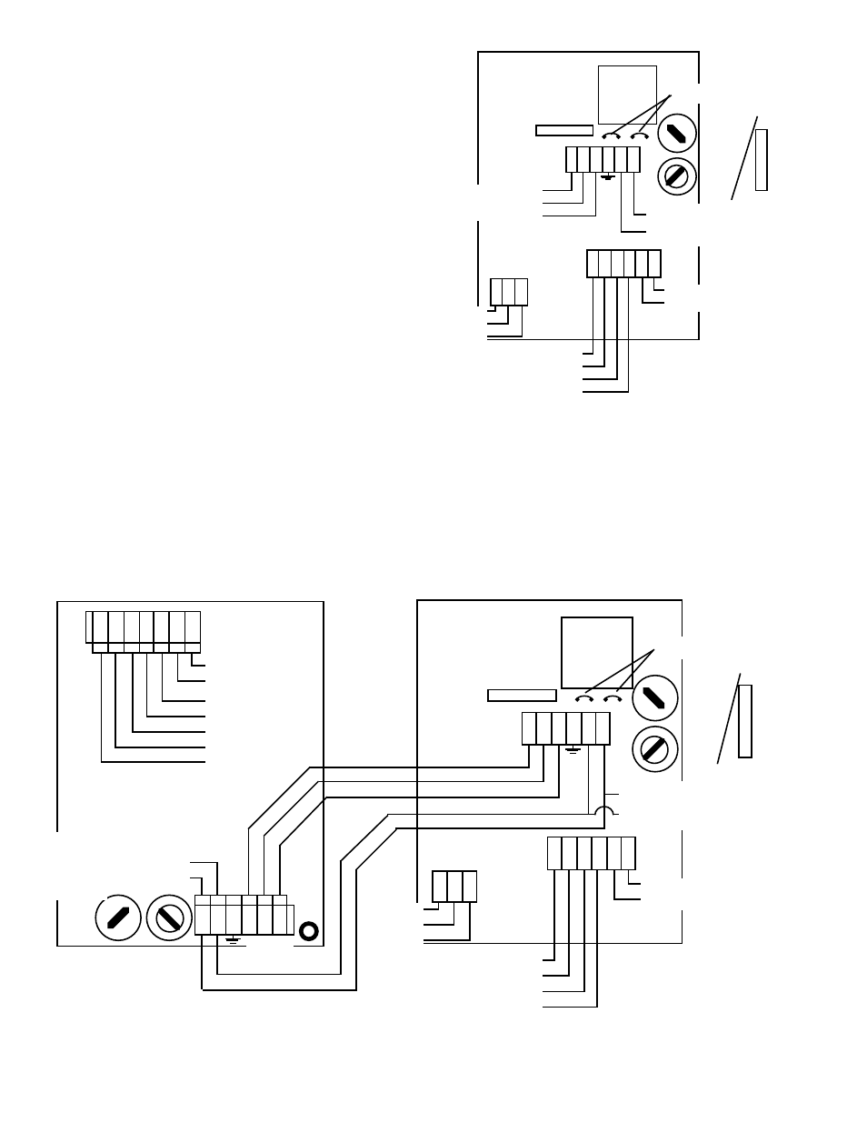
AQUASWITCH II™
ELECTRICAL CONNECTION DIAGRAM
Figure II.E.2
AQUASWITCH™
POWER BOARD
SENSOR
L N
0-10VDC
OUTPUT
NEU
GRN
RED
WHT
BLK
(+)
(-)
CONTROL
RELAY
NEU-WHT
LINE-BLK
MONITOR/CONTROLLER
MAIN CIRCUIT BOARD
}
{
}
FUSE
115/230
SWITCH
SOLENOID
VALVE
OUTPUT
POWER
BANK B
BANK A
BLEED
COM
MAIN
INPUT
POWER
GRN
ORN
WHT
LINE / +DC
(BLK)
NEUTRAL / -DC
(WHT)
NC
NO
COM
GRD
C
AC
ALARM
RELAY
NO
COM
NC
FUSE
1/8 Amp
AGC 1/8
WHT
BLK
SOLENOID
INPUT
POWER
LINE
NEUTRAL
BK B
BK A
BLD
COM
LOGIC
BOARD
CONNECTION
FUSE*
115/230
SWITCH
TRANSFORMER
*115/230VAC
FUSE
100mA
(T.10A) 5X20
Slow Blow/
Time Delay
*24VAC
FUSE
250mA
(T.25A) 5X20
Slow Blow/
Time Delay
115/230
JUMPERS
OR
}
}
MAIN
INPUT
POWER
FROM AS
POWER
BOARD
Figure II.E.1
ASI
ELECTRICAL CONNECTION DIAGRAM
AQUASWITCH™
POWER BOARD
TRANSFORMER
FUSE*
115/230
SWITCH
SOLENOID
VALVE
OUTPUT
POWER
BANK B
BANK A
BLEED
COM
MAIN
INPUT
POWER
LINE / +DC
(BLK)
NEUTRAL / -DC
(WHT)
NC
NO
COM
GRD
C
AC
ALARM
RELAY
NO
COM
NC
FUSE
1/8 Amp
AGC 1/8
WHT
BLK
SOLENOID
INPUT
POWER
LINE
NEUTRAL
BK B
BK A
BLD
COM
LOGIC
BOARD
CONNECTION
INPUT FROM
CONTROLLER
RELAY
115/230
JUMPERS
OR
}
}
{
{
{
{