Orange blue brown – Myron L Aquaswitch II User Manual
Page 29
C .
TEMPERATURE MODULE
-TP
Temperature Module ordered with Monitor/controller.
TPO
Temperature Module Kit ordered separately.
Requires; CSXX-TP sensor, Special Order, i.e. CS10-TP
or CS40-TP, see sensor data sheet.
.
1 . D E S C R I P T I O N
The Temperature Module (TP) gives the Monitor/controller more
flexibility for the user by being in the same package.
The Temperature Module is driven by the main display output and
is very simple to install.
The Temperature Module and Temperature Sensor SYSTEM
utilize a unique 3 wire technique by which errors are greatly
reduced.
The Temperature Module has its own 0-5VDC output.
TPO kit comes with all items necessary to install and operate: TP
Module; front panel harness with switch, bezel, cap and two o-
rings (006 & 008); and TEMPERATURE label (# LTEMP).
NOTE: Requires the CSXX-TP sensor temperature wires be
routed directly to the TP/TPO CB.
Specifications
±200°C (±200°F Special Order Only)
Accuracy:
±0.2 w/ICE
±0.5 w/out ICE
Display Resolution = 0.1
Output:
0-5 VDC
Connections - 2
Sensor Input:
Cond/TDS, RES sensor with SPECIAL Platinum
RTD added or 1000
Ω
RTD temperature sensor.
Connections - 3 (3 wire for increased
accuracy over long distances)
Calibration
Zero and Full Scale, FS (0 & 5 VDC): Factory Set
Simple pots
Display (CAL): Full Scale, FS (199.9) Factory Set
Simple pot
Operates on safe ±5 VDC supplied by the Main CB.
2. INSTALLATION
Briefly -
The Temperature Module replaces the plastic display retainer
plate attached to the front panel.
The display harness plugs into the Temperature Module instead of
the display.
The -TP sensor leads are connected to the Temperature Module.
See figure III.C.1.
The display switch is installed in the lower front panel as shown in
figure III.C.4.
A “TEMPERATURE” label is added to lower front panel next to the
Display Select switch as shown in figure III.C.4.
!
CAUTION - READ FOLLOWING CAREFULLY
WARNING: BEFORE STARTING, IF
AQUASWITCH II
IS INSTALLED, ENSURE THE POWER IS OFF.
FAILURE TO DO SO COULD CAUSE DAMAGE TO THE
INSTRUMENT, AND COULD BE HARMFUL OR FATAL
TO PERSONNEL. ONLY QUALIFIED PERSONNEL
SHOULD INSTALL OR SERVICE ELECTRICAL
E Q U I P M E N T .
Physical
If the front panel has all ready been removed from the enclosure
skip to 3.
1.
Using a standard slot screwdriver remove the two (2)
screws on the front panel.
2.
Carefully wiggle the front panel and pull gently toward
you. Do not pull more than about 8 inches/20CM or you
could damage the wiring harness.
3.
Turn the front panel around so that the back side is
facing you.
4.
Using a standard slot screwdriver remove the four (4)
screws holding the plastic display retainer plate to the
front panel. When the screws have been removed, the
plastic display retainer plate and the display will be
free from the front panel.
5.
Set front panel down or carefully allow to hang from the
harness. Do not drop as the harness connector will pull
out allowing the front panel to fall.
6.
While holding the display and the plastic display retainer
plate, carefully remove the display harness connector.
Do not drop the display.
7.
Remove and discard the plastic display retainer plate.
8.
Insert display connector pins into the Temperature
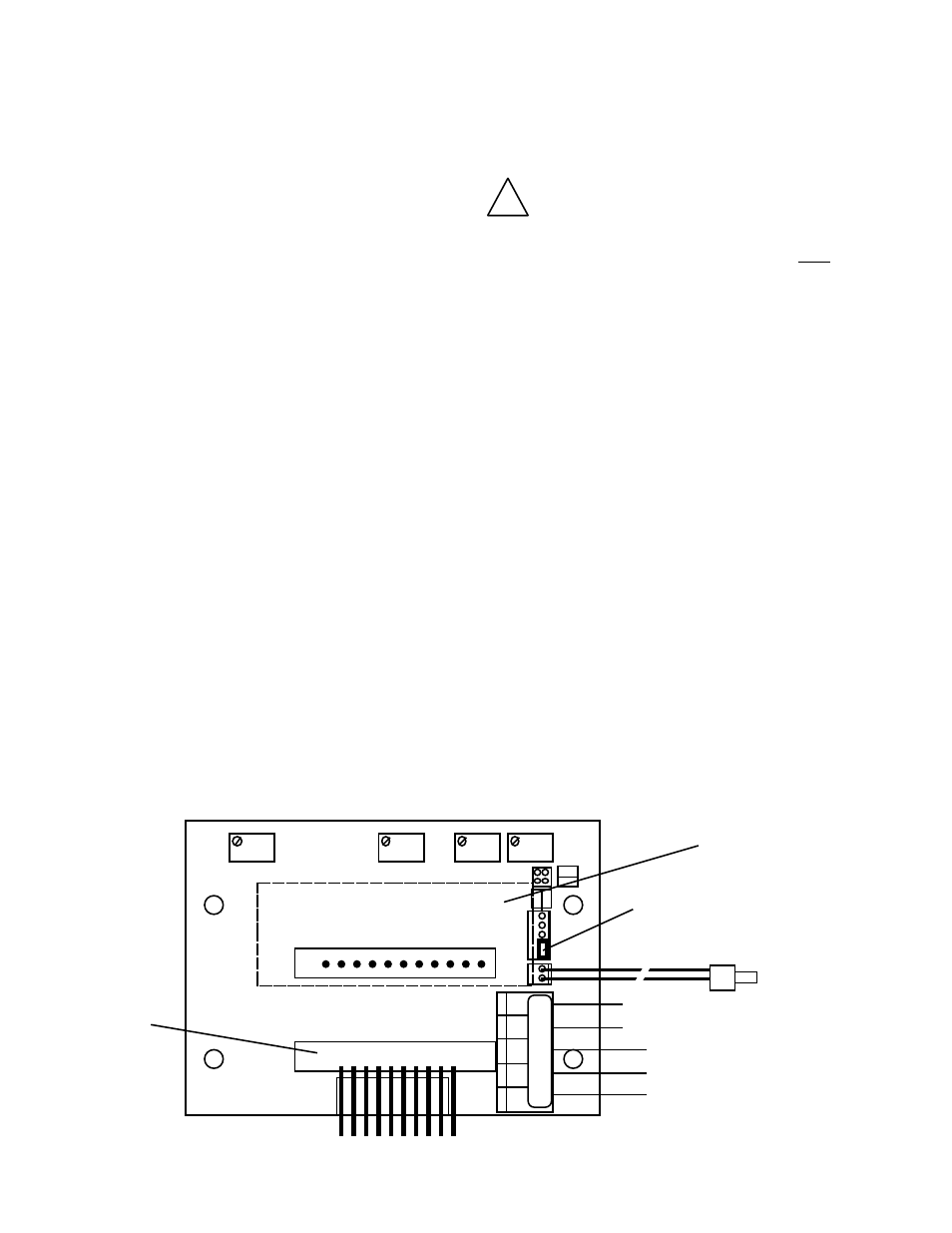
Module female connector. See figure III.C.1.
26
Figure III.C.1
FS
ZERO
D I S
S P 2
H Y S 2
DISPLAY CONNECTION
DISPLAY
0-5VDC
OUTPUT
(-)
(+)
BRN
BLU
INC
INC
DEC
DEC
TEMPERATURE
SENSOR INPUT
Orange
Blue
Brown
RECONNECT
DISPLAY
HARNESS
HERE
DISPLAY IS ON THE
BACK SIDE OF THE
TEMPERATURE
MODULE
JUMPER
OR
BR BL OR - +
SPC
TP/TPO - TEMPERATURE MODULE
TEMP
CONTROL
HARNESS
DISPLAY
SELECT
+
0-5VDC
-