Aquaswitch ii, Figure iii.c.3, Switch and o-ring assembly figure iii.c.4 – Myron L Aquaswitch II User Manual
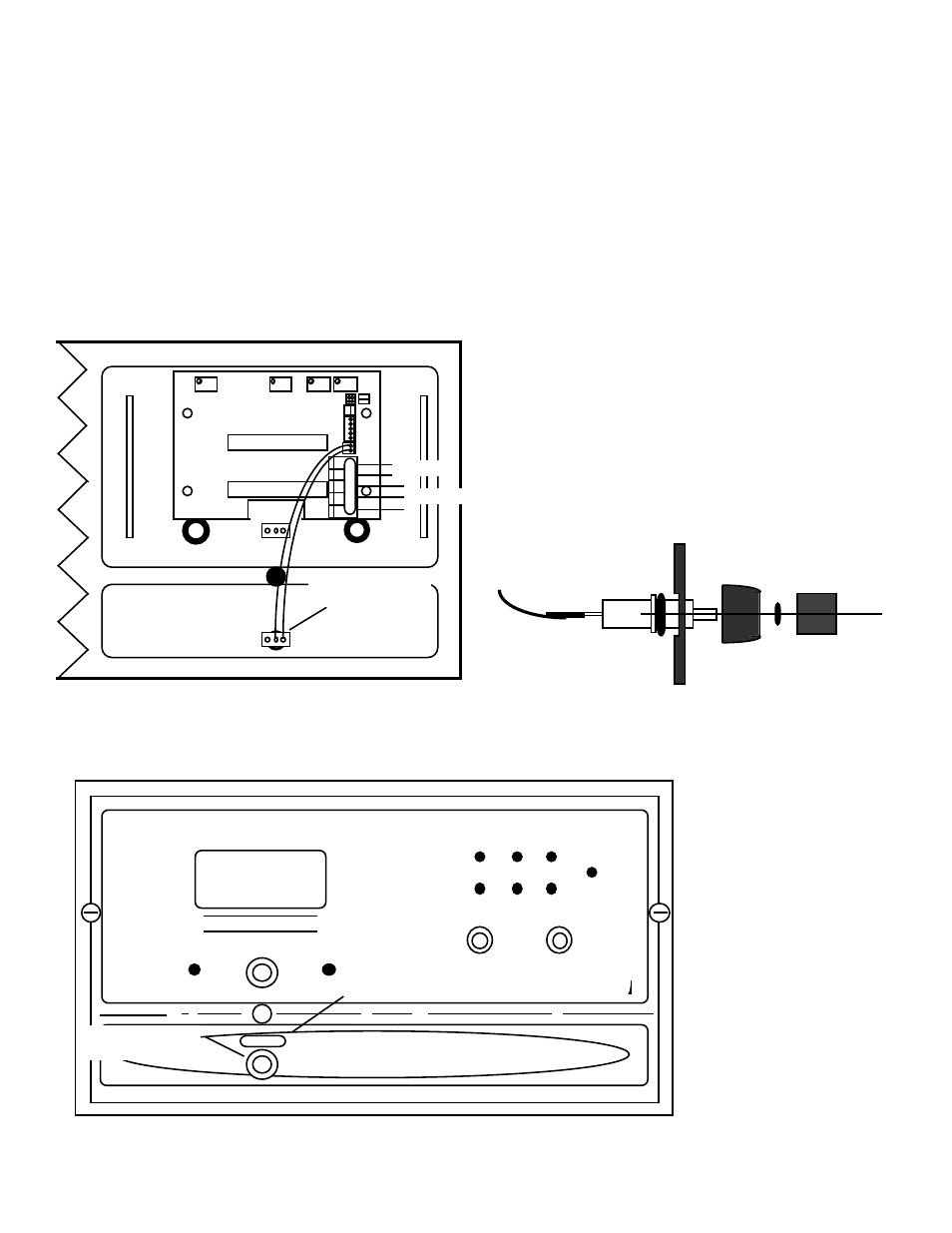
Page 30: Figure iii.c.2 aquaswitch ii front panel rear view
9.
While holding the front panel, align the display to the
opening and at the same time, align the Temperature
Module mounting holes to the front panel.
10. Reconnect display harness with leads down as shown in
figures III.C.1 & III.C.2.
11. Reinstall the four (4) screws and tighten.
Display Select Switch installation
1.
Using a small sharp knife or 1/4” (6.35mm) drill, carefully
cut open the lower center hole of the front panel, when
viewed from the back. See figure III.C.2.
2.
Install push-button display switch into this hole and
tighten bezel. See figures III.C.2 & III.C.4.
3.
Install push-button/cap on switch.
WARNING
: There are two (2) o-rings installed on the switch, one
(1) on the threaded shank and the other is under the push button.
Both of these must be re-installed to maintain IP64/NEMA 3
ratings. See figure III.C.3.
4.
Place “TEMPERATURE” label ABOVE the switch as
shown in figure III.C.4.
Electrical
1.
Connect the display switch harness to the Temperature
Module as shown in figure III.C.1.
2.
Connect the Temperature Sensor leads to the
Temperature Module as labeled in figure III.C.1.
CAUTION: The input connectors require only a small
screwdriver or a pen to push on the release levers. The release
levers may be broken or damaged if not pushed straight toward the
CB. DO NOT push the release levers sideways. Follow the color
code as labeled.
3.
Connect 0-5 VDC output, if desired.
4.
To test, turn power ON.
5.
Press “TEMPERATURE” front panel switch, display will
show the temperature of the sensor.
6.
Turn power OFF.
7.
Continue or reinstall the front panel and tightly secure
both retaining screws, see REASSEMBLY below.
27
Figure III.C.3
FRONT PANEL
BEZEL
PUSH BUTTON
O-RING
O-RING
SWITCH
SWITCH and O-RING ASSEMBLY
Figure III.C.4
AQUASWITCH II
BANK SWITCH
ALARM RESET
BANK A
BANK B
BLEED
WATER QUALITY
IN USE GOOD POOR
MEGOHMS - CM
SET POINT
HIGH
LOW
TEMPERATURE
Switch Location
TEMPERATURE
Label Location
TEMPERATURE
Figure III.C.2
AQUASWITCH II
FRONT PANEL
Rear View
TEMPERATURE
Switch Location
FS
ZERO
DIS
SP2
HYS2
DISPLAY CONNECTION
DISPLAY
(-)
(+)
BRN
BLU
INC
INC
DEC
DEC
TEMPERATURE
SENSOR INPUT
0-5VDC
OUTPUT
DISPLAY
SELECT
+
0-5VDC
-
SPC
TEMP
SENSOR
BR BL OR - +
TEMP
CONTROL
HARNESS
MYRON L
COMPANY