Myron L Aquaswitch II User Manual
Page 17
a. USP 25 MODIFICATION
(No Temperature Compensation)
This simple modification will allow your
AQUASWITCH II
Monitor/controller to meet the USP 25 requirements by defeating
the normal temperature compensation circuit thus giving
“uncompensated” readings as required.
Specifications:
As required to meet USP25.
Installation
Briefly -
For Resistivity models, two resistors are installed in place of the
sensor “temperature” sensing leads.
For Conductivity/TDS models, a resistor is installed in place of the
sensor “temperature” sensing leads.
The extra sensor leads are either cut off or the ends are wrapped
in tape to prevent shorting.
!
CAUTION - READ FOLLOWING CAREFULLY
WARNING: BEFORE STARTING, IF THE
AQUASWITCH II
IS INSTALLED, ENSURE THE
P O W E R I S OFF. FAILURE TO DO SO COULD CAUSE
DAMAGE TO THE INSTRUMENT, AND COULD BE
HARMFUL OR FATAL TO PERSONNEL. ONLY
QUALIFIED PERSONNEL SHOULD INSTALL OR
SERVICE ELECTRICAL EQUIPMENT.
Requirements:
For Resistivity; one 100k
Ω
1% resistor, and one 5.49K
Ω
1%
resistor, user supplied or may be ordered from the Myron L
Company.
For Conductivity/TDS; one 10k
Ω
1% resistor, user supplied or
may be ordered from the Myron L Company.
NOTE: When opening instrument, remove front cover with care;
a ribbon cable connects the front panel and main board. If the
front panel has all ready been removed from the enclosure skip to
#4.
1.
Using a standard slot screwdriver remove the two (2)
screws on the front panel.
2.
Carefully wiggle the front panel and pull gently toward
you. Do not pull more than about 8 inches/20CM or you
could damage the wiring harness.
3.
Turn the front panel around so that the back side is
facing you and set aside.
4.
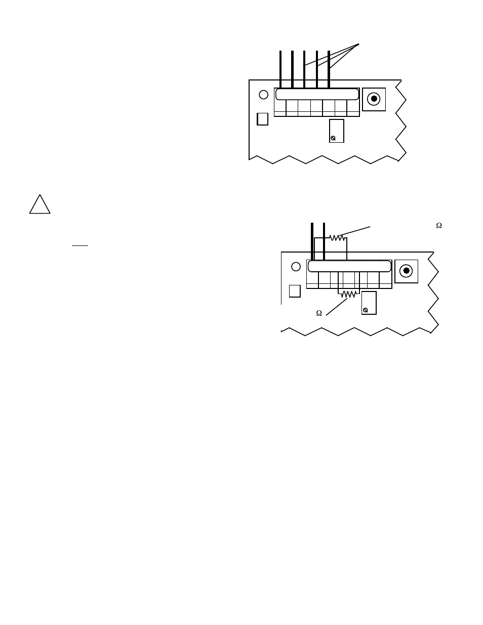
For Resistivity Monitor/controllers;
a.
If sensor is installed, locate and remove the BLACK
(BK), RED (RD), and the NEUTRAL (NU) leads
from MAIN Circuit Board, as shown in figure
II.E.5.
b.
Cut off or tape BLACK (BK), RED (RD), and the
NEUTRAL (NU) leads from sensor.
c.
Install 100k
Ω
resistor at BLACK (BK) and GREEN
(GN) connector locations, as shown in figure
II.E.6.
d.
Install 5.49k
Ω
resistor at RED (RD) and the
NEUTRAL (NU) connector locations, as shown in
figure II.E.6.
For Conductivity/TDS Monitor/controllers;
a.
If sensor is installed, locate and remove the RED
(RD) and the GREEN (GN) leads from MAIN
Circuit Board, as shown in figure II.E.7.
b.
Cut off or tape RED (RD) and the GREEN (GN)
leads from sensor.
c.
Install 10k
Ω
resistor at RED (RD) and the GREEN
(GN) connector locations, as shown in figure
II.E.8.
5.
Carefully reinstall the front panel, bottom first. Ensure no
wires have been pinched between enclosure and front
panel.
6.
Reinstall the two (2) screws and tighten.
7.
To operate, turn power ON.
NOTE: Recalibration will require both the solution and sensor be
at 25°C for maximum accuracy.
14
Figure II.E.5
R E M O V E T H E S E
T H R E E L E A D S
FS SW
3 S
S E N S O R L E A D S
CAL
Resistivity Main CB Assembly
Figure II.E.6
S E N S O R L E A D S
FS SW
3 S
CAL
Resistivity Main CB Assembly
INST ALL 1 00 K
R E S I S T O R H E R E
I N S T A L L 5 . 4 9 K
R E S I S T O R H E R E
BK WT RD GN NU R- R+
BK WT RD GN NU R- R+