Aquaswitch ii, Aquaswitch i – Myron L Aquaswitch II User Manual
Page 13
1.
Select mounting site location. Mark and drill the required
mounting holes. For hole drilling locations, see figure
II.B.1.
2.
Insert the 1/4" X 20 screws into the holes from the side
opposite the mounting site.
3.
Hold the Monitor in place while starting and tightening the
mounting screws.
3. PANEL MOUNTING
A panel mounting fastening kit is provided with all
AQUASWITCH
’s. Panel mounting will require the use of the
fastening kit's two (2) 4-40 mounting screws/nuts or two (2) #4 x
1/2" sheet metal screws. See figures II.B.1 & II.B.2. for panel
cutout dimensions.
1.
Select your mounting location. Mark the appropriate
panel cutout and complete the necessary panel cut.
10
Figure II.B.3
D I M E N S I O N S I N
INCHES
( M I L L I M E T E R S )
AQUASWITCH II
SURFACE
MOUNT
5.00
(127)
3.75
(95)
0.75
(19)
3.77
(96)
9.85
(250)
0.31 DIA 2PL
(8)
2.00
(51)
0.60 DIA
(15)
0.50 DIA
(13)
0.68 DIA 2 PL
(22)
01.03 DIA 2 PL
(29)
9.85
(250)
0.75
(19)
3.90
(99)
5.00
(127)
0.50
(13)
0.63 THK
(1.6)
5.10
(129)
9.92
(252)
10.19
(259)
2.57
(65)
0.13
(3)
0.12 RAD MAX 4PL
(3)
PANEL
CUTOUT
0.13 2PL
(3)
10.81
(275)
6.00
(152)
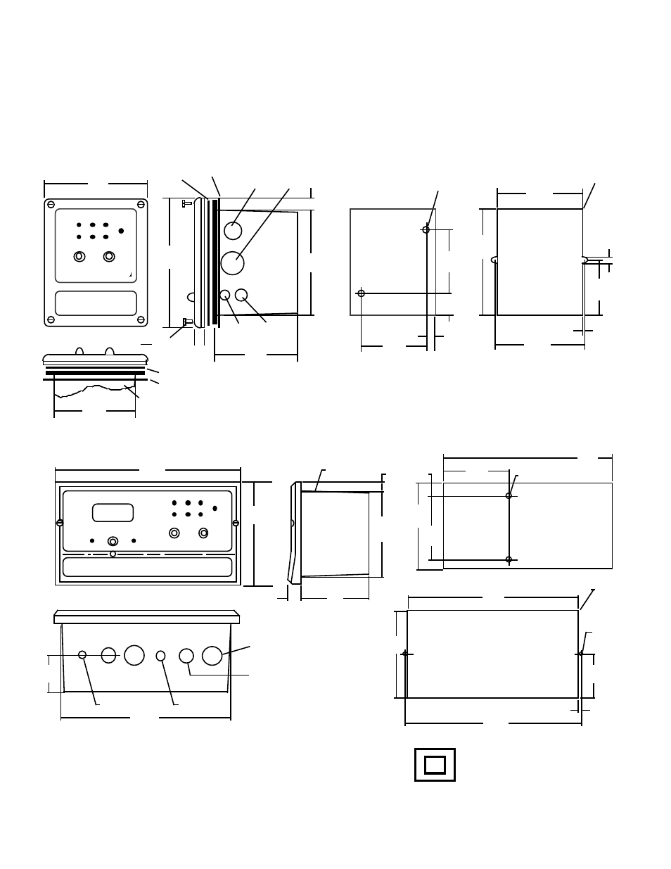
AQUASWITCH
II
SURFACE AND PANEL MOUNTING DIAGRAMS
DOUBLE INSULATED
NOT TO SCALE
SURFACE AND PANEL MOUNTING DIAGRAMS
NOT TO SCALE
DIMENSIONS IN INCHES
(MILLIMETERS)
4.80
(122)
0.63 THK
(16)
3.10
(79)
0.40
(10)
SURFACE
MOUNT
1.05
(27)
2.84
(72)
0.31 DIA, X2
(8)
5.00
(127)
3.96
(101)
0.13 RAD MAX, X4
(3)
0.113
(3)
2.54
(64)
4.17
(106)
0.11
(3)
PANEL
CUTOUT
6.00
(152)
0.5
(13)
0.88 DIA
(22)
1.13 DIA
(29)
0.53
(14)
4.94
(126)
0.60 DIA
(15)
3.78
(96)
0.50 DIA
(13)
Figure II.B.2
Face Plate Gasket
Panel Gasket
Face Plate Gasket
Panel Gasket
6-32x3/8" x4
AQUASWITCH
I
AQUASWITCH I
3.89
(99)