Iv. operating procedures, Aquaswitch i – Myron L Aquaswitch II User Manual
Page 35
IV. OPERATING PROCEDURES
The front panel illustrations, switch and indicator operational
descriptions have been provided to assist the user in identifying
and operating the
AQUASWITCH I
&
AQUASWITCH II
Monitor/controllers.
Section IV.A provides the operational descriptions for each of the
AQUASWITCH I
and
AQUASWITCH II
switch and indicator
controls.
Section IV.B provides the user with recommended Setup
procedures
Section IV.C provides the user with recommended checkout
procedures.
A .
SWITCH AND INDICATOR CONTROLS
1 .
AQUASWITCH I
BANK A/B “IN USE” Indicators
The amber “IN USE” LED indicator light is ON only when its
respective Bank’s solenoid valve is energized.
NOTE: The units have been designed so that only one (1) Bank
(either A or B) can be in use at any time.
Water Quality “GOOD” Status Indicators
The green “GOOD” status LED light indicators are ON when their
respective Bank’s water quality is acceptable or ABOVE
Controller Set Point - Resistivity (the reverse is true for
Conductivity - BELOW).
Water Quality “POOR” Status Indicators
The red “POOR” status LED light indicators are ON only when
their respective Bank’s water quality is unacceptable or BELOW
Controller Set Point - Resistivity (the reverse is true for
Conductivity - ABOVE).
“BLEED” Indicator Light
The amber “BLEED” LED indicator light is ON only when the
AQUASWITCH
is in its Purge Cycle (Bleed/Process Water
valve(s) are activated).
“BANK SWITCH” Push Button
When the “BANK SWITCH” is pressed, the
AQUASWITCH
automatically switches Banks, i.e. turns OFF the currently
selected Bank and turns ON the alternate Bank, i.e. Bank A to
Bank B or visa versa.
“ALARM RESET” Push Button
When the-”ALARM RESET” switch is pressed, the
AQUASWITCH
will automatically turn OFF the Alarm.
2 .
AQUASWITCH II
The
AQUASWITCH II
incorporates all of the features listed
above in the
AQUASWITCH I
plus those listed below.
3 1/2 Digit LCD
The 3 1/2 Digit LCD provides a continuous readout of the water
being controlled. A 3 1/2 digit “backlit” LCD is available as an
option.
“HIGH/LOW” Set Point Indicators
The green LED indicator light is ON only when the resistance of
the water is ABOVE the Controller’s internal Set Point.
The red LED indicator light is ON only when the resistance of the
water is BELOW the Controller’s internal Set Point.
NOTE: The reverse is true for Conductivity.
“SET POINT CHECK” Switch
When the “SET POINT CHECK” switch is pressed, the internal Set
Point reading is immediately displayed on the LCD.
3 .
AQUASWITCH II
O P T I O N S
Piezo Alarm
Audible alarm sounds off automatically when the set point is
reached. Figure IV.A.2. shows the location of this option. See
section III.B.
Backlit Display
A 3 1/2 digit “backlit” LCD is available.
Temperature Module adds the ability to momentarily display the
solution temperature by pressing a switch mounted on the from
panel as shown in figure IV.A.2. see section III.C for details.
32
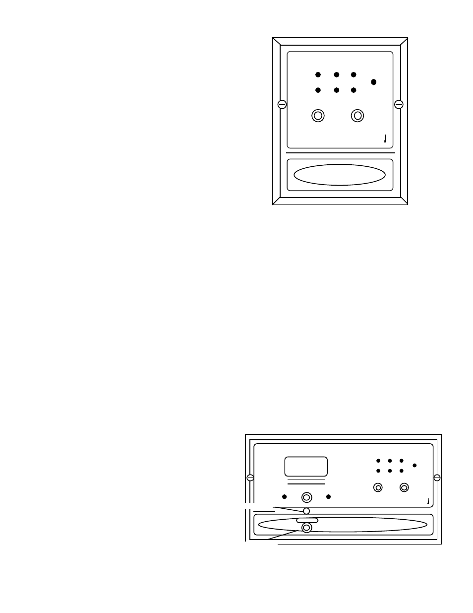
Figure IV.A.1
AQUASWITCH I
BANK SWITCH
ALARM RESET
BANK A
BANK B
BLEED
IN USE GOOD POOR
WATER QUALITY
AQUASWITCH I
FRONT PANEL
Figure IV.A.2
AQUASWITCH II
BANK SWITCH
ALARM RESET
BANK A
BANK B
BLEED
WATER QUALITY
IN USE GOOD POOR
MEGOHMS - CM
SET POINT
HIGH
LOW
AQUASWITCH II
FRONT PANEL
TEMPERATURE
TEMPERATURE
OPTION
PIEZO ALARM
MYRON L
COMPANY
MYRON L
COMPANY