Myron L Aquaswitch II User Manual
Page 16
The following procedures are to be used to install the
AQUASWITCH II
to 115 VAC main power source. For the
procedures to install the optional 230 VAC main power source, the
user must first complete the installation procedures in Section
II.E.3. Failure to do so could result in damage to equipment and/or
property.
1.
Verify that the main power source is turned "OFF" or
disconnected.
2.
Using a standard slot screwdriver remove the two (2)
screws on the front panel.
3.
Carefully wiggle the front panel and pull gently toward
you. Do not pull more than about 8 inches/20CM or you
could damage the wiring harness.
4.
Turn the front panel around so that the back side is
facing you and set aside for now.
5.
Using the enclosure cutouts, install the proper wire and
watertight cable restraint (not provided) to comply with
local electrical codes.
6.
Neatly connect wires to the
AQUASWITCH II
's
connectors*, as shown in figures II.E.2.
*CAUTION: The input power connectors require only a small
screwdriver, or a pen to push on the release levers†. The release
levers may be broken or damaged if not pushed straight toward
the circuit board. DO NOT push the release levers sideways.
† Early versions have screw terminals.
3 . 1 1 5 / 2 3 0 V A C C O N V E R S I O N
Before turning power ON to the
AQUASWITCH
ensure the
proper input voltage has been selected. For the
AQUASWITCH
I
, see figures II.E.1 & II.E.3. This is required in TWO locations on
the
AQUASWITCH II
, see figures II.E.2 & II.E.3. Failure to do
so will blow the fuse(s). It could, under some conditions, cause
injury and damage the instrument voiding the warranty.
On the early model
AQUASWITCH
Power Board the conversion
must be accomplished by desoldering and resoldering a buss wire
jumper as shown in figure II.E.3, (to desolder and resolder the
JUMPERS, the circuit board (CB) must be removed from the
enclosure), or may be accomplished as shown in figure II.E.4.
Later models have switches, see section II.E.3.b and figure
II.E.2.
NOTE: Both early and later models function exactly the same.
II.E.3.a. Early Model Power Boards with
Buss Wire JUMPERS
This requires extreme care as circuit board may be damaged if
improperly attempted.
1.
Locate the jumpers below the transformer.
2.
Cut jumpers in location as shown in figure II.E.4.
3.
Carefully, bend leads toward each other (center) as
shown in figure II.E.4.
4.
Solder the ends of the leads together.
II.E.3.b. Later Model Power Boards with SWITCH
1.
Locate switch next to the fuse holder.
2.
Using a screwdriver, turn switch to required voltage.
I I . E . 3 . c .
AQUASWITCH II
Main Control Board
ALL
AQUASWITCH II
Main Control Boards have a switch. See
figure II.E.2.
1.
Locate switch next to the fuse holder.
2.
Using a screwdriver, turn switch to required voltage.
4. CONNECTING THE SENSOR CABLE
This section provides the procedure to properly wiring the sensor.
1.
Place the SENSOR interface cable and user supplied
watertight cable restraint into the enclosure's
appropriate access hole.
2.
Install the SENSOR cable wire to comply with local
electrical codes.
3.
Follow the color code as marked. See figure II.E.2.
*CAUTION: The sensor connectors require only a small
screwdriver or a pen to push on the release levers. The release
levers may be broken or damaged if not pushed straight toward
the circuit board. DO NOT push the release levers sideways.
13
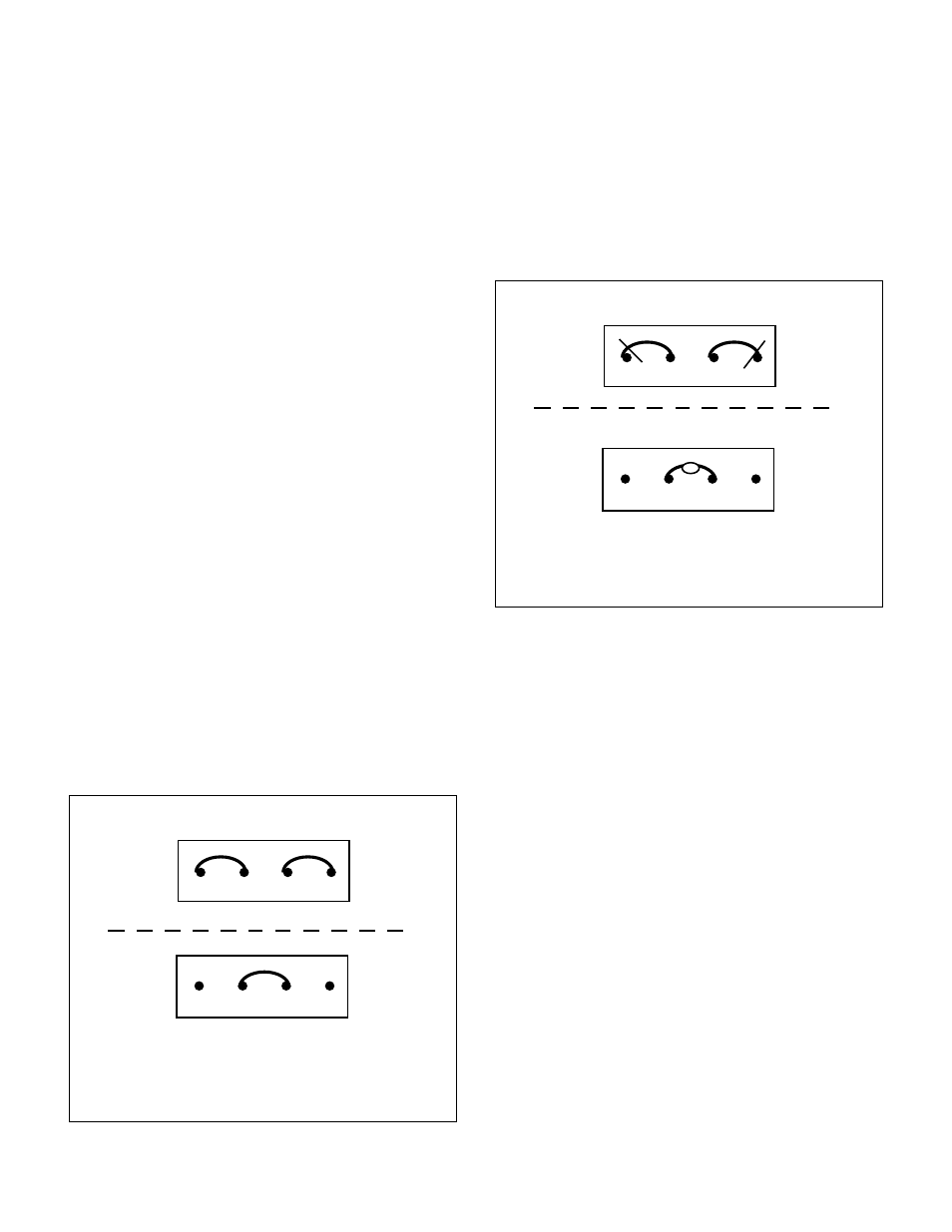
EARLY MODEL POWER BOARD
115/230 VAC JUMPER CONVERSION
115 VAC
230 VAC
JUMPERS LOCATED UNDER TRANSFORMER
Figure II.E.3
Figure II.E.4
JUMPERS LOCATED UNDER TRANSFORMER
EARLY MODEL POWER BOARD
115/230 VAC JUMPER CONVERSION
115 VAC
230 VAC
Cut and carefully bend leads toward center
Solder ends together