Myron L Aquaswitch II User Manual
Page 26
4. CONVERTING A CURRENT
TO A VOLTAGE
Current measuring devices actually measure voltage, but have an
internal resistor as shown in figures III.A.1 & III.A.2 and are
scaled to display in current. If you have a voltage input
instrument and you wish to utilize the current from the 4A (4-
20mA) Module, the following will help you to make this conversion.
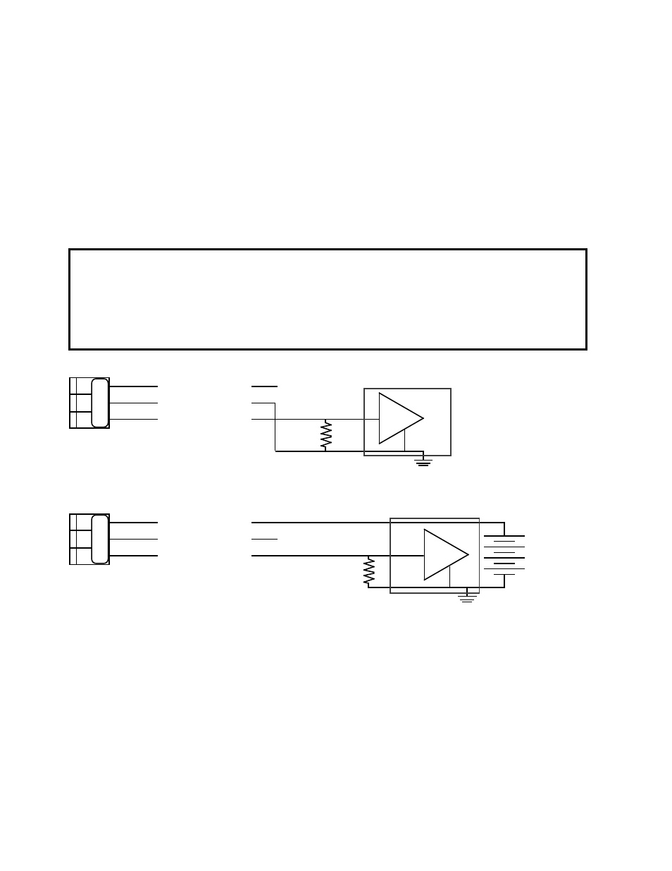
To convert a 4-20 mA current output to operate or drive a voltage
input device it is necessary to install a LOAD resistor across the
input terminals as shown in figures III.A.6 & III.A.7. The value of
the resistor is chosen to match the input voltage range, i.e. 0-10
Volts requires a 500
Ω
resistor and will produce a 2 to 10 input
voltage. This floating zero is useful to indicate a broken 4-20 input
wire when the indication is zero volts.
For other input ranges, divide the input voltage range by 0.02, the
answer will be in ohms.
NOTE: The tolerance of the load resistor directly affects the
accuracy of the resulting voltage, i.e. 5% resistor = 5% error.
23
Figure III.A.7
(+)
(-)
+
-
(+)
SIGNAL OUT
POWER OUT
POWER IN
+
Remote - Powered
VOLTAGE INPUT INSTRUMENT
+ 35 VDC
MAXIMUM
N
EXTERNAL LOAD
RESISTOR
Figure III.A.6
For an input voltage range of:
10.0 Volts
the resistor value is
500 ohms
indicates
2.0 V
@ 4 mA.
5.0 Volts
“
250 ohms
“
1.0 V
“
1.0 Volts
“
50 ohms
“
0.2 V
“
100 millivolts
“
5 ohms
“
20 mV “
10 millivolts
“
0.5 ohms
“
2 mV
“
(+)
(-)
+
-
(+)
SIGNAL OUT
POWER OUT
POWER IN
+
Self - Powered
N
EXTERNAL LOAD
RESISTOR
VOLTAGE INPUT INSTRUMENT
SO PO PI
SO PO PI