Dv self - powered n remote - powered – Myron L Aquaswitch II User Manual
Page 25
4.
If not, adjust the CAL control marked “4mA” until the
DVM indicates 4mA, see figure III.A.5.
5.
Press the Full Scale Test Switch, the DVM should
indicate 20 milliamps.
6.
If not, adjust the CAL control marked “20mA” until the
DVM indicates 20mA. See figure III.A.5.
7. Calibration is complete
8.
Turn power OFF.
9.
Reconnect sensor wires to sensor terminal block as
shown in figure III.A.4.
10. Carefully reinstall the front panel, bottom first, ensure no
wires have been pinched between enclosure and front
panel.
11. Reinstall the two (2) screws and tighten.
12. To operate, turn power ON.
22
Figure III.A.5.
(+)
(-)
+
-
(+)
SIGNAL OUT
POWER OUT
POWER IN
+
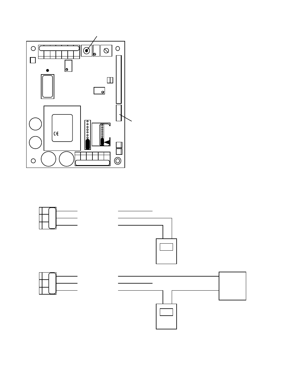
DV
Self - Powered
N
Remote - Powered
(+)
(-)
+
-
(+)
SIGNAL OUT
POWER OUT
POWER IN
+
DV
Remote
Power
Supply
N
+
-
Figure III.A.4.
MONITOR/CONTROLLER CIRCUIT
BOARD ASSEMBLY
CHS
GND
HYS1
SP1
FUSE*
115/
230
TRANSFORMER
D I S
CAL
3S
PA
RA
INC
DEC
SPC
0-10VDC
4-20
751 756
752 757
753 758
754 759
MYRON L
COMPANY
4 - 2 0
CONNECTOR
CONNECT 4AO
HARNESS HERE
FS SW
FULL SCALE
TEST SWITCH
-11
0-20m
Ω
UP
}
BK WT RD GN NU R- R+
PWR C GD NC NO CM
REMOVE TO
INSTALL
SECOND
RELAY
SO PO PI
SO PO PI