Warning ! 11, Solenoid valve mounting diagram – Myron L Aquaswitch II User Manual
Page 14
2.
Carefully unfasten and separate the
AQUASWITCH
'
s
front panel from its enclosure.
3.
Disconnect all panel cable(s)/wires from the
AQUASWITCH's
Control board.
4.
Slide the enclosure through the panel cutout
until its flange contacts the panel.
5.
Insert mounting screws through the flange
mounting holes and tightly secure.
6.
Reconnect all panel cable(s)/wires and reinstall the front
panel.
C .
SOLENOID VALVE INSTALLATION
There are many types of solenoid valves. The user must decide
which type is best suited for the specific application. The
following is an example installation of one type of valve,
1.
Insert the pilot valve unit so that the systems’ INFLOW
source and OUTFLOW process piping connecting ends
are inserted into the valve as shown in figure II.C.1.
2.
Repeat step until all appropriate pilot valve units have
been installed.
NOTE: The number of pilot valves used will be based upon the
user’s desired application.
24VAC
INTERCONNECTING
WIRES
OPTIONAL INFLOW
INFLOW
OUTFLOW
PILOT
VALVE
OPERATES
NORMALLY
OPEN
MANUAL OVERRIDE
ADJUSTABLE
FLOW CONTROL
OPERATES
NORMALLY
CLOSED
SOLENOID VALVE MOUNTING DIAGRAM
D .
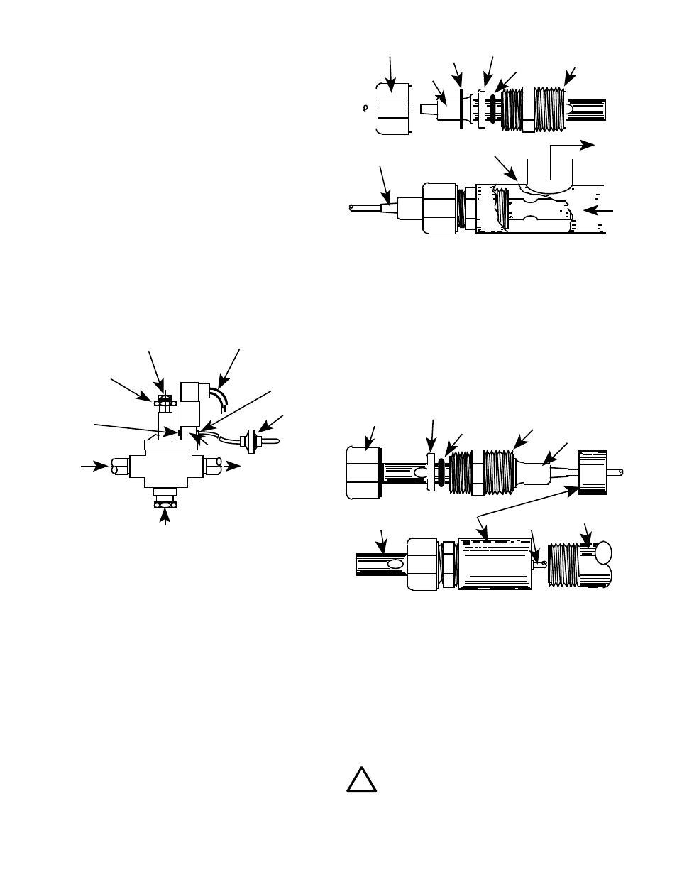
S E N S O R I N S E R T I O N / I M M E R S I O N M O U N T I N G
The SENSOR’s mounting orientation must provide a continuous
and adequate circulation flow to prevent the trapping of air
bubbles within the Sensor’s electrode area (CS10 shown in
figures II.D.1 & II.D.2). Failure to do so will result in conditions
that will prevent the Sensor from functioning properly.
1. INSERTION MODE (in-line installation)
Use approved sealant, i.e. Teflon tape as required.
1.
Verify that the Sensor’s Fitting assembly is properly
assembled as shown in figure II.D.1.
2.
Insert the Sensor Fitting assembly into the "T" fitting with
electrode aligned as shown in figure II.D.1. and tightly
2. IMMERSION OR DIP SENSOR ASSEMBLY
Use approved sealant, i.e. Teflon tape as required.
1. Verify that the Sensor’s Fitting assembly is properly
assembled as shown in figure II.D.2.
2. Insert and pull the Sensor’s cable through the extension
tube and then tightly attach extension tube to Sensor
assembly as shown in figure II.D.2.
Figure II.D.2
IMMERSION OR DIP SENSOR ASSEMBLY
CABLE
SENSOR TIP
COUPLING
3/4" NPT
EXTENSION TUBE
PLASTIC
WASHER
O-RING
THREADED FITTING
3/4" FNPT
FLANGE
E .
ELECTRICAL INSTALLATION
The
AQUASWITCH I
and
AQUASWITCH II
require the user
to follow separate electrical installation procedures. In addition,
based on the user’s solenoid voltage specifications, the user will
be required to connect Solenoid Power.
NOTE: All cable watertight restraints are user supplied.
!
WARNING !
11
Figure II.D.1.
INSERTION MODE ASSEMBLY
SECURING NUT
FLANGE
SS
WASHER
PLASTIC
WASHER
O-RING
THREADED FITTING
3/4" FNPT
"T" FITTING
CABLE
OUT
IN