Figure v.a.1, Primary component identification – Myron L Aquaswitch II User Manual
Page 3
QUICK SET POINT ADJUSTMENT -
S e e S e c t i o n I V . B . 2 .
The set point setting is based upon the user's particular water
purity specifications or requirements.
1. While pressing the "SET POINT" switch, turn the Set
Point #1 adjustment screw (see figure V.A.1) until the
desired set point value is indicated on the display.
HYSTERESIS (DEAD BAND) ADJUSTMENT -
S e e S e c t i o n I V . B . 3 .
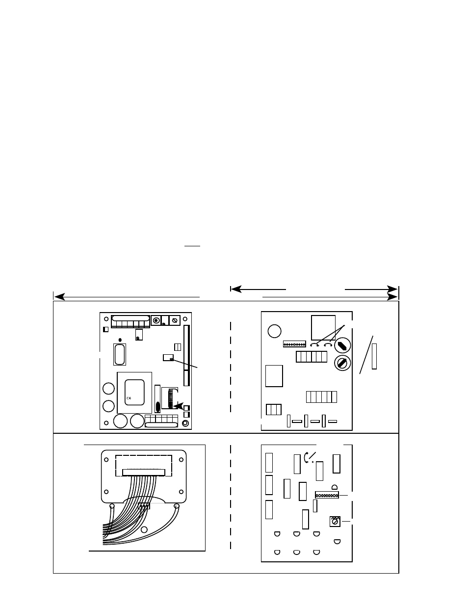
PRIMARY COMPONENT IDENTIFICATION -
Section V.A
.
Review the figure below to familiarize yourself with the different
circuit boards and component locations. The diagram has the
second alarm/control module option installed.
“PURGE CYCLE” CALIBRATION PROCEDURE
Section V.B.
“ALARM RESET” MODE CHANGE PROCEDURE
Section V.C.
QUICK CALIBRATION - Section V.D
.
WARNING: When performing calibration procedures,
the technician must take extreme care to avoid
contacting the circuitry other than the CALibration
control. Failure to do so could result in damage to
the equipment, property and/or personal injury.
The following assumes the front panel has been
removed and the power is ON.
ELECTRONIC CALIBRATION (CIRCUIT ONLY) -
S e e S e c t i o n V . D . 1 .
Full Scale Calibration V.D.1.a.
1.
Press and hold the Full Scale Test switch. The display
should indicate Full Scale for the particular range
selected, i.e. 0-20 M
Ω
should indicate 20. If not, set to
Full Scale with the CALibration control.
2.
Turn power O F F .
3.
Re-install front panel as described in “REASSEMBLY”.
4.
To operate, turn power ON.
10VDC Calibration - See Section V.D.1.b.
USING STANDARD SOLUTIONS - See Section V.D.2.
The BEST method of verifying and recalibrating your
conductivity/TDS
AQUASWITCH II
is with NIST traceable
Standard Solution (available from the Myron L Company).
Because it includes the sensor, the entire system is recalibrated.
NOTE: Since standard solution calibrations are NOT practicable
with resistivity models, another means of verification or
calibration of resistivity models is to use the transfer standard
method, using a hand-held or portable instrument capable of
resistivity measurements, such as the Myron L Ultrameter™. See
section V.C.4 for description.
SENSOR SUBSTITUTE CALIBRATION -
S e e S e c t i o n V . D . 3 .
TRANSFER STANDARD METHOD - See Section V.D.4.
21 may 03
Figure V.A.1
AQUASWITCH II
MAIN MONITOR/CONTROLLER BOARD
E
N
C
L
O
S
U
R
E
PRIMARY COMPONENT IDENTIFICATION
AQUASWITCH II
AQUASWITCH I
AQUASWITCH
LOGIC BOARD
F
R
O
N
T
P
A
N
E
L
LOW
DISPLAY
HARNESS
DISPLAY
DISPLAY CONNECTOR
RED
GREEN
SET POINT
SWITCH
TO MONITOR/
CONTROLLER
CIRCUIT BOARD
DISPLAY
CONNECTOR
AQUASWITCH II
DIGITAL DISPLAY
CABLE
CONNECTS TO
POWER BOARD
PURGE CYCLE
CONTROL
AQUASWITCH
POWER BOARD
TRANSFORMER
FUSE*
115/230
SWITCH
AQUASWITCH™
POWER BOARD
NC
NO
COM
GRD
C
AC
NO
COM
NC
FUSE
1/8 Amp
AGC 1/8
BK B
BK A
BLD
COM
LOGIC
BOARD
CONNECTION
RELAY
115/230
JUMPERS
OR
ALARM OUTPUT
CONNECTORS
*115/230VAC
FUSE
100mA
(T.10A) 5X20
Slow Blow/
Time Delay
*24 VAC/24 VDC
FUSE
250mA
(T.25A) 5X20
Slow Blow/
Time Delay
TRANSFORMER
FUSE*
1 1 5 /
230
751 756
752 757
753 758
754 759
HYS1
SP1
FS SW
DIS
INC
DEC
CAL
-11
0-20m
Ω
UP
}
3S
SPC
CALIBRATION
CONTROL
DISPLAY
HARNESS
CONNECTOR
DISPLAY
CALIBRATION
CONTROL
RANGE
MODULE
4-20
CONNECTOR
BK WT RD GN NU R- R+
REMOVE TO
INSTALL
SECOND
RELAY
PWR C GD NC NO CM
BK B
WHT
STANDARD
ALARM RESET
ENABLE JUMPER
MYRON L
COMPANY