Myron L Aquaswitch II User Manual
Page 32
7.
If not, adjust the calibration control marked “ZERO” (see
figure III.C.1 for location).
8.
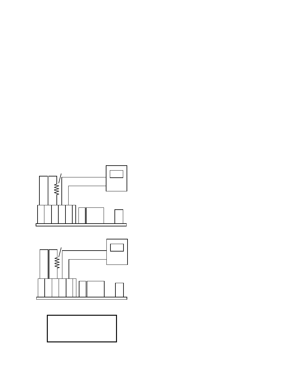
Install SPAN resistor (1758.56
Ω
) across sensor
terminals BL and OR. See figure III.C.9.
9.
The DVM should indicate 5 . 0 volts.
10. If not, adjust the calibration control marked “FS” (see
figure III.C.1 for location) until the DVM indicates 5 . 0
volts as shown in figure III.C.9.
11. Press the front panel TEMPERATURE select switch, the
display should indicate 1 9 9 . 9 as shown in figure
III.C.10.
12. If not adjust the calibration control marked “D I S ” (see
figure III.C.1 for location) until the reading is 1 9 9 . 9 .
13. Calibration is complete.
14. Turn power OFF.
15. Remove DVM from 0-5 VDC.
16. Remove resistor and jumper by pressing on each
Phoenix connector release lever*.
17. Reconnect sensor leads as labeled.
18. Reconnect 0-5 VDC output leads as labeled.
19. Continue or reinstall the front panel and tightly secure
both retaining screws, see REASSEMBLY below.
*CAUTION: The sensor input and 0-5 VDC output connectors
require only a small screwdriver or a pen to push on the release
levers. The release levers may be broken or damaged if not
pushed straight toward the CB. DO NOT push the release levers
sideways.
c. System Calibration
By following these steps the complete temperature system,
module and sensor, may be calibrated to better than ±0.2°
centigrade accuracy. This procedure is similar to the electronic
calibration except the sensor is attached and is allowed to
equilibrate in “ICE” water before adjusting the ZERO calibration
control.
NOTE: One of the above electronic calibration procedures, TPC
Module or precision resistors, must be performed BEFORE the
system calibration is performed. This is required to preset the
span between zero and full scale.
1.
Ice must be crushed in water to form a very thick slurry.
A slurry is that condition where the water to ice ratio is
such that only sufficient water is present to allow easy
stirring. At this point, the temperature of the water will
be 0.000°C.
2.
Immerse sensor and cable approximately 2” (50mm) into
slurry.
3.
Allow to equilibrate. Slurry must be constantly stirred.
4.
Continue stirring until no further change in temperature is
observed on the display.
5.
Adjust TP Module ZERO calibration control to 000.0.
6.
Continue or reinstall the front panel and tightly secure
both retaining screws, see REASSEMBLY below.
REASSEMBLY
1.
Carefully reinstall the front panel, bottom first. Ensure no
wires have been pinched between enclosure and front
panel.
2.
Reinstall the two (2) screws and tighten.
3.
To operate, turn power ON.
29
Figure III.C.9
JUMPER
BR BL OR - +
Connect DVM leads as shown.
DV
-
+
5.0
1758.56
Ω
RESISTER
Figure III.C.8
DV
-
+
0.0
JUMPER
BR BL OR - +
Connect DVM leads as shown.
1000.0
Ω
RESISTER
Figure III.C.10
199.9
FRONT PANEL DISPLAY