Pulsafeeder Polyfeeder EN User Manual
Page 31
6.7.2.3.2.2
The Polyf
system wa
series con
running.
6.7.2.3.2.3
The B/B+
threshold
6.7.2.3.2.4
The B Ser
the maxim
rotatmeter
located on
for low flo
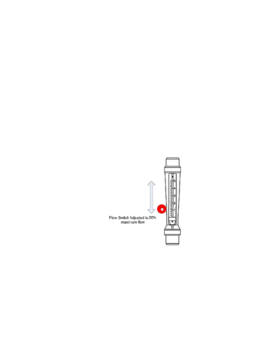
6.7.2.3.2.5
The B++
programm
Setting th
feeder B-serie
ater flow. Th
ntrollers. Sett
Setting th
++ series contr
for low water
B series T
ries controller
mum flow allo
r in the prima
n the sensor.
ow. Be sure t
Figure
B++ Serie
series control
matically throu
he Water Flo
es must be pro
hese flows are
ing the water
he Water Flo
rollers allow t
r conditions.
Threshold
r platform use
owed in the pr
ary H20 flow p
Sliding the s
to retighten th
6-7-2-3-2-4 B
es Threshold
ller platform h
ugh the user i
ow (BSeries o
ogrammed wi
e read from th
flow rate ma
ow Alarm Th
the user to ac
es water flow
rimary water
path. The flo
sensor up or d
he hex screw w
B-Series Cont
d
has a flow me
nterface.
31
only)
ith the current
e system’s ro
ay be accompl
reshold Leve
tivate the wat
switches that
stream. The f
ow alarm thres
down the rotam
when adjustm
troller Adjustm
eter in the prim
t primary and
otameters in or
lished by pres
el and Recog
ter flow alarm
t are set durin
flow switch is
shold may be
meter body al
ment is compl
ment of Water
mary path tha
d secondary (t
rder to provid
ssing the DOW
gnition Time
m and then set
ng factory inst
s located on th
e increased by
llows the user
lete.
r Flow Alarm
at allows the s
otal dilution s
de pump pacin
WN ARROW
t an appropria
tallation at ~2
he left hand si
y loosening th
r to set the des
m Threshold
system to set t
streams)
ng for B-
W while
ate alarm
20 percent of
ide of the
he hex nut
sired alarm
the threshold