2 control input requirements and wiring details – Pulsafeeder Polyfeeder EN User Manual
Page 17
17
6.6.2 Control Input Requirements and Wiring Details
6.6.2.1 Remote Start Input Contact Requirements
The Polyfeeder may be started remotely via a PLC/SCADA system or a remote located start/stop switch.
The user must provide a dry contact closure signaling the Polyfeeder to start (contact closed) or stop
(contact open). The contact or switch must be rated for 24 VDC and 1 amp.
6.6.2.2 B-Series Remote Start Controller Wiring
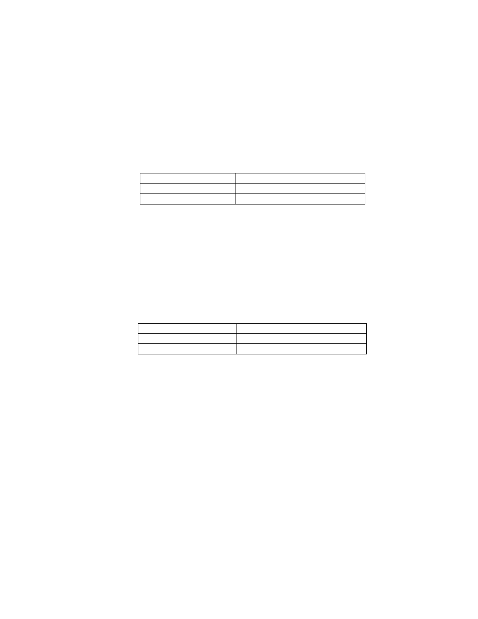
Signal Terminal
Block
Location
Contact Side A
TB3-1300
Contac Side B
TB3-1790
Table 6-6-2-1 B-series controller Remote Start Contact Wiring
6.6.2.3 Remote Analog Input Requirements
The Polyfeeder B-series controller provides remote polymer concentration control via a two-wire analog
input. This analog input presents a 250 ohm impedance to the PLC/SCADA system. The PLC/SCADA
system must provide 4-20mA. Current sources must be sourcing capable externally loop powered
outputs. The analog control signal should be routed in a separate conduit and 20 AWG twisted pair
w/shield is recommended. The shield shall be tied to the customer PLC/SCADA system ground.
The wiring connection for this signal is listed below
Signal
Terminal Block Location
Positive TB3-3740W
Negative (Common)
TB3-1302
Table 6-6-2-3 Analog Polymer Demand input
6.6.2.4 Programmable Contact Output Requirements
The Polyfeeder B-series controller provides 3 programmable normally open dry contact output
connections capable of 5A @ 250VAC or 5A @ 30VDC. These outputs are programmable to allow the
user to signal the following system conditions:
1. SYSTEM RUNNING/STOPPED
2. LOCAL_REMOTE (Control Mode)
3. LOW POLYMER FLOW
4. LOW WATER FLOW
16 AWG wiring is recommended with 600 volt insulation rating.