Agilent Technologies Agilent 4396B User Manual
Page 94
Measuring
Electrical
Length
The
analyzer
electronically
implements
a
function
similar
to
the
mechanical
\line
stretchers"
of
earlier
analyzers
.
The
analyzer's
electrical
length
correction
function
simulates
a
variable
length
lossless
transmission
line
.
This
simulated
line
can
be
added
or
removed
from
a
receiver's
input
to
compensate
for
interconnecting
cables
or
other
connections
.
In
this
example
,
this
function
is
used
to
measure
the
electrical
length
of
a
test
device
.
Measurement
Setup
With
the
same
connection,
instrument
settings
,
and
calibration
used
in
the
previous
example
(see
\Measurement
Setup
"
in
\Measuring
Transmission
Characteristics
of
a
Filter"),
make
the
following
changes:
1.
Press
4
Chan
1
5
4
F
ormat
5
NNNNNNNNNNNNNNNNN
PHASE
to
display
the
phase
trace
on
channel
1.
2.
Press
4
Displa
y
5
NNNNNNNNNNNNNNNNNNNNNNNNNNNNNNNNNNNNNNNNNNNNNNNNNN
DUAL
CHAN
ON
off
to
NNNNNNNNNNNNNNNNNNNN
on
OFF
.
3.
Press
4
Span
5
50
4
M/
5
to
zoom
the
passband
trace
on
the
display
.
Measurement
If
the
trace
needs
to
be
rescaled,
press
4
Scale
Ref
5
NNNNNNNNNNNNNNNNNNNNNNNNNNNNNNNN
AUTO
SCALE
.
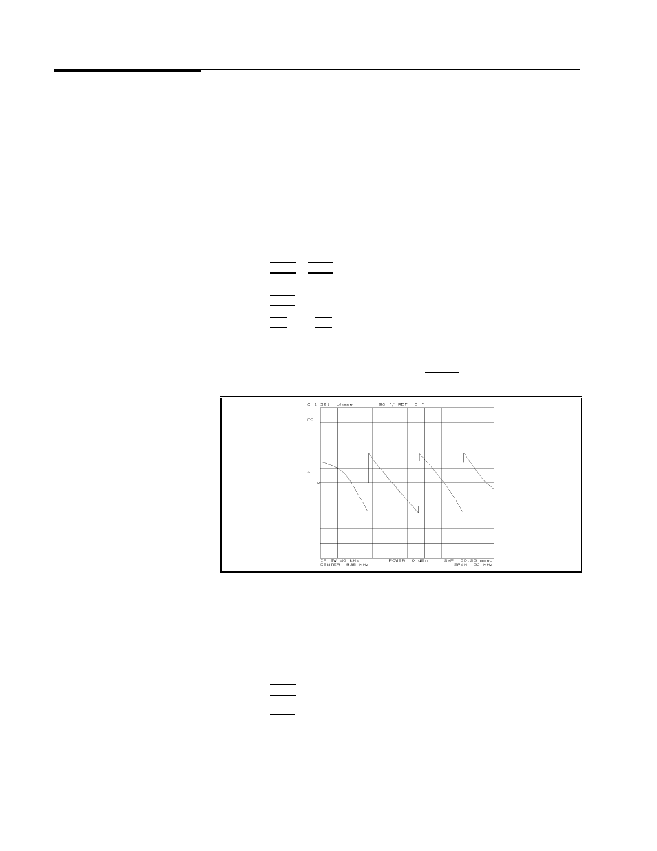
Figure
5-7.
Phase
Response
of
a
Dielectric
Filter
Over
a
50
MHz
Span
Electrical
Length
A
djustment
The
linearly
decreasing
phase
is
due
to
the
DUT's
electrical
length.
This
length
is
measured
by
electronically
adding
length
to
the
R
input
to
compensate
for
it.
1.
Press
4
Chan
2
5
to
activate
channel
2.
2.
Press
4
Ma
rk
er
5 .
Then
move
the
marker
to
any
of
the
points
where
the
sloping
trace
crosses
the
center
.
Place
the
marker
on
the
sloping
portion
of
the
trace
,
not
on
the
vertical
phase
\wrap-around."
5-8
Network
Measurement
Examples