Agilent Technologies Agilent 4396B User Manual
Page 113
Absolute
Output
Level
Measurement
The
analyzer
can
show
the
characteristics
input
level
versus
output
level
by
using
the
absolute
measurement
capability
in
the
network
analyzer
mode
.
1.
Press
4
Sw
eep
5
NNNNNNNNNNNNNNNNNNNNNNNNNNNNNNNNNNNNNNNNNNNNNNNNNN
CHAN
COUP
on
OFF
to
NNNNNNNNNNNNNNNNNNNNNNNNNNNNNNNNNNNNNNNNNNNNNNNNNN
CHAN
COUP
ON
off
to
couple
the
sweep
parameters
of
both
channels
.
2.
Press
4
Ma
rk
er
5
N
NNNNNNNNNNNNNNNNNNNNNNNNNNNNNNNNNNNNNNNNNNNNNN
MKR
COUP
on
OFF
to
N
NNNNNNNNNNNNNNNNNNNNNNNNNNNNNNNNNNNNNNNNNNNNNN
MKR
COUP
ON
off
to
couple
the
marker
between
both
channels
.
3.
Press
4
Chan
2
5
4
Meas
5
NNNNN
B
to
select
the
absolute
measurement
at
the
B
input.
4.
Press
4
Displa
y
5
NNNNNNNNNNNNNNNNNNNNNNNNNNNNNNNNNNNNNNNNNNNNNNNNNN
DATA
MATH
[DATA]
NNNNNNNNNNNNNNNNNNNN
OFFSET
.
Then
input
the
value
of
the
attenuator
that
is
connected
between
the
DUT
and
the
B
input.
In
this
example
measurement,
a
30
dB
attenuator
is
used.
Therefore
,
enter
30
4
21
5 .
5.
Press
4
Scale
Ref
5
NNNNNNNNNNNNNNNNNNNNNNNNNNNNNNNN
AUTO
SCALE
if
the
trace
needs
to
be
rescaled.
6.
The
analyzer
displays
the
input
versus
output
power
levels
.
The
marker
shows
the
input
and
output
power
levels
at
the
01
dB
gain
compression
point.
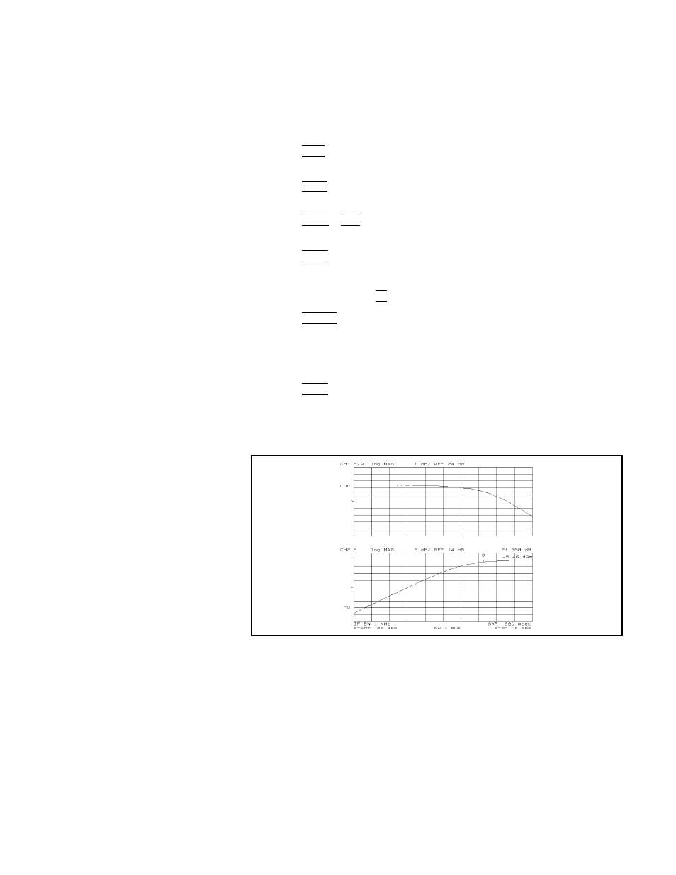
7.
Press
4
Displa
y
5
NNNNNNNNNNNNNNNNNNNNNNNNNNNNNNNNNNNNNNNNNNNNNNNNNN
DUAL
CHAN
on
OFF
to
NNNNNNNNNNNNNNNNNNNN
ON
off
to
display
both
channel
(see
Figure
5-24).
Note
that
you
must
subtract
3
dB
from
the
input
value
readout.
This
is
necessary
because
the
input
signal
is
attenuated
by
the
power
splitter
that
is
between
the
RF
OUT
and
the
DUT
.
Figure
5-24.
Input
vs
.
Output
P
ower
Level
at
the
01
dB
Gain
Compression
P
oint
Network
Measurement
Examples
5-27