Agilent Technologies Agilent 4396B User Manual
Page 84
Burst
Signal
Measurement
This
measurement
requires
that
option
1D6
be
installed
in
the
analyzer
.
A
summary
of
how
to
determine
gate
delay
and
gate
length
settings
for
dierent
signals
is
contained
at
the
end
of
this
example
.
T
est
Signal
The
following
test
signal
is
used
in
this
example:
Pulse
period
(pri )
=
100
s
(pulse
repetition
frequency
prf
is
10
kHz
)
Duty
ratio
is
80%
(
pulse
width
is
80
s)
RF
frequency
is
960
MHz
Measurement
Setup
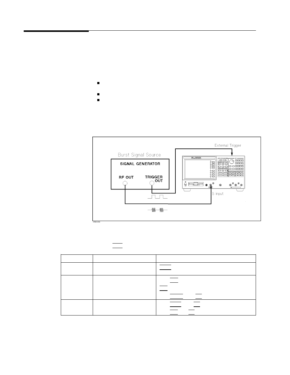
Connection
Setup
the
analyzer
as
shown
in
Figure
4-19 .
Figure
4-19.
Burst
Signal
Measurement
Setup
Analyzer
Settings
Press
4
Preset
5 .
Then
set
the
analyzer's
controls
as
follows:
Desired
Settings
K
ey
Strokes
A
ctive
Channel
Block
Select
channel
1
4
Chan
1
5
(default)
Measurement
Block
Select
Spectrum
Analyzer
Press
4
Meas
5
FFFFFFFFFFFFFFFFFFFFFFFFFFFFFFFFFF
ANALYZER
TYPE
F
FFFFFFFFFFFFFFFFFFFFFFFFFFFFFFFFFFFFFFFFFF
SPECTRUM
ANALYZER
Select
S
input
4
Meas
5
FFFFFFFFFFFFFFFFFFFFFFFFFF
SPECTRUM:S
(default)
Set
RBW
to
100
kHz
Press
4
Bw/A
vg
5
100
4
k/m
5
Sweep
Block
Center
frequency
960
MHz
Press
4
Center
5
960
4
M/
5
Span
frequency
10
MHz
Press
4
Span
5
10
4
M/
5
4-16
Spectrum
Measurement
Examples