Agilent Technologies Agilent 4396B User Manual
Page 88
Measuring
Transmission
Characteristics
of
a
Filter
Insertion
loss
and
gain
are
ratios
of
the
output
to
input
signals
.
The
following
procedure
measures
the
insertion
loss
and
gain
of
a
836
MHz
dielectric
bandpass
lter
.
This
measurement
can
be
used
to
obtain
the
key
lter
parameters
.
Measurement
Setup
Connection
Set
up
the
analyzer
as
shown
in
Figure
5-1.
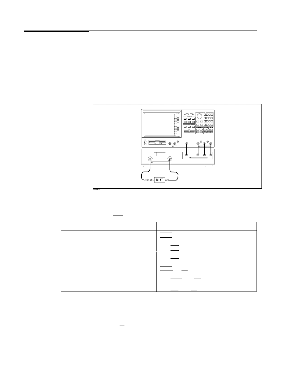
Figure
5-1.
Transmission
Measurement
Setup
Analyzer
Settings
Press
4
Preset
5 .
Then
set
the
analyzer's
controls
as
follows:
Desired
Settings
K
ey
Strokes
A
ctive
Channel
Block
Select
channel
1
4
Chan
1
5 (default)
Measurement
block
Select
Network
Analyzer
Press
4
Meas
5
FFFFFFFFFFFFFFFFFFFFFFFFFFFFFFFFFF
ANALYZER
TYPE
FFFFFFFFFFFFFFFFFFFFFFFFFFFFFFFFFFFFFFFFF
NETWORK
ANALYZER
Select
S
21
(or
B/R)
measurement
Press
4
Meas
5
FFFFFFFFFFFFFFFFFFFFFFFFFFFFFFFFFFFFFFFFFFFFFFFF
Trans:FWD
S21
[B/R]
Select
LOG
MA
G
format
4
F
ormat
5
FFFFFFFFFFFFFFFFFFF
LOG
MAG
(default)
IF
BW
3
kHz
4
Bw/A
vg
5
3
4
k/m
5
Sweep
block
Center
frequency
836
MHz
Press
4
Center
5
836
4
M/
5
Span
frequency
200
MHz
Press
4
Span
5
200
4
M/
5
P
erforming
Calibration
P
erform
a
frequency
response
calibration
for
this
measurement
as
follows:
1.
Press
4
Cal
5
NNNNNNNNNNNNNNNNNNNNNNNNNNNNNNNNNNNNNNNNNNNN
CALIBRATE
MENU
NNNNNNNNNNNNNNNNNNNNNNNNNN
RESPONSE
.
5-2
Network
Measurement
Examples