Agilent Technologies Agilent 4396B User Manual
Page 103
Impedance
Measurement
The
amount
of
power
re ection
from
a
device
is
directly
related
to
the
impedance
values
of
both
the
device
and
the
measuring
system.
In
fact,
each
value
of
the
re ection
coecient
(0)
uniquely
denes
a
device
impedance
.
F
or
example:
0=0
occurs
when
the
device
and
test
set
impedance
are
the
same
.
A
short
circuit
has
a
re ection
coecient
of
0=1
6
180
(=01).
An
open
circuit
has
a
re ection
coecient
of
0=1
6
0
(=1).
Every
other
value
for
0
also
corresponds
uniquely
to
a
complex
device
impedance
,
according
to
the
equation
Z
n
=
1
+
0
1
0
0
Where
Zn
is
the
DUT
impedance
normalized
to
(that
is
,
divided
by)
the
measuring
system's
characteristic
impedance
(usually
50
or
75
).
The
network
analyzer
has
a
default
impedance
of
50
.
T
o
set
the
impedance
to
75
,
press
4
Cal
5
NNNNNNNNNNNNNN
MORE
NNNNNNNNNNNNNNNNNNNN
SET
Z0
.
The
network
analyzer
uses
the
formula
above
to
convert
the
re ection
coecient
measurement
data
to
impedance
data.
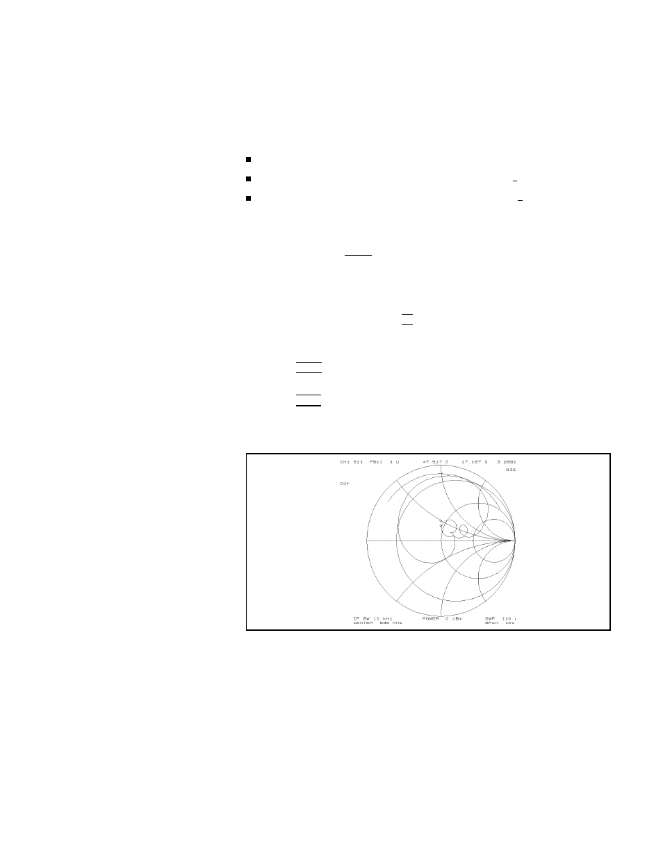
1.
Press
4
F
ormat
5
NNNNNNNNNNNNNNNNN
SMITH
.
The
display
shows
the
complex
impedance
of
the
DUT
over
the
frequency
range
selected.
2.
Press
4
Ma
rk
er
5
to
turn
on
the
marker
.
Then
use
the
knob
to
read
the
resistive
and
reactive
components
of
the
complex
impedance
at
any
point
along
the
trace
.
The
maker
displays
a
complex
impedance
readout.
Figure
5-16.
Impedance
Measurement
Network
Measurement
Examples
5-17