ADS Technologies Wireless Cable Modem Gateway SBG1000 User Manual
Page 33
27
SBG1000 User Guide
X
Exit
Overview Installation Troubleshooting Contact
FAQ Specifications Glossary License
Configuration: Basic Gateway TCP/IP Wireless Print Server USB
6
If necessary, seat an anchor in each hole.
Use M5 x 38 mm (#10-16 x 1
1
/
2
inch) screws with a flat underside and maximum screw head diameter of
10.5 mm to mount the SBG1000.
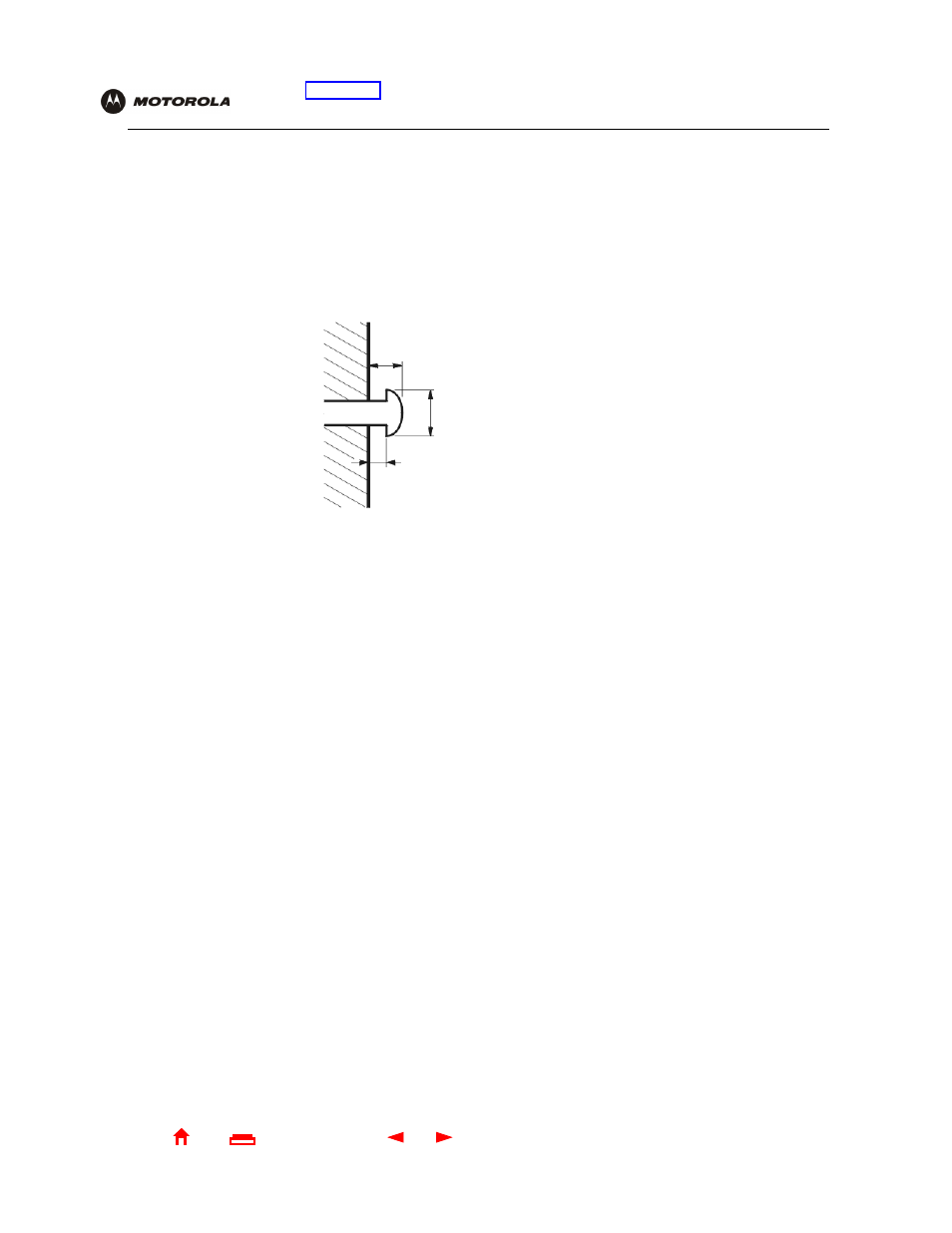
7
Using a screwdriver, turn each screw until part of it protrudes from the wall, as shown:
•
There must be .16 inches (4.0 mm) between the wall and the underside of the screw head.
•
The maximum distance from the wall to the top of the screw head is 7.6 mm (.3 in).
8
Place the SBG1000 so the keyholes on the back of the unit are aligned above the mounting screws.
If you are using the built-in antennas, be sure you do not damage them.
9
Slide the SBG1000 down until it stops against the top of the keyhole opening.
.3 inches (7.6 mm) maximum
.4 inches (10.5 mm) maximum
.16 inches (4.0 mm)