Installing the unit (only for experts) – Karcher SB Wash Oel 50-10 F VA User Manual
Page 25
-
11
Notice
The equipment may only be installed by an
–
mechanic of Kärcher
–
or an from Kärcher authorized individu-
al
The following requirements are necessary
in order to install the equipment:
–
Horizontal, plane surface with firm base
admeasuring 845 x 725 mm next to the
SS wash.
–
Water connection with pipe separator
according to EN 1717m, for output data,
see "Technical Data". Follow national
regulations (DVGW in Germany).
–
By customer, lockable, access for the
wash customer emergency - off- main
switch.
–
Light at the washing area according to
the national requirements, in order to
assure safe working for the customer
when dark.
–
Power and water supply according to
the measuring sheet.
–
By operation in the winter, an isolated/
heated water supply sytem must be
guaranteed.
–
Drain water shaft and required drain
water disposal.
–
Drill fastening holes according to the
measurement sheet.
Unpack the equpiment and dispose of the
packing material properly.
Line up the equipment on the level ar-
ea.
Fix with the material included. Use the
inclosed spacer and set up the equip-
ment horizontal.
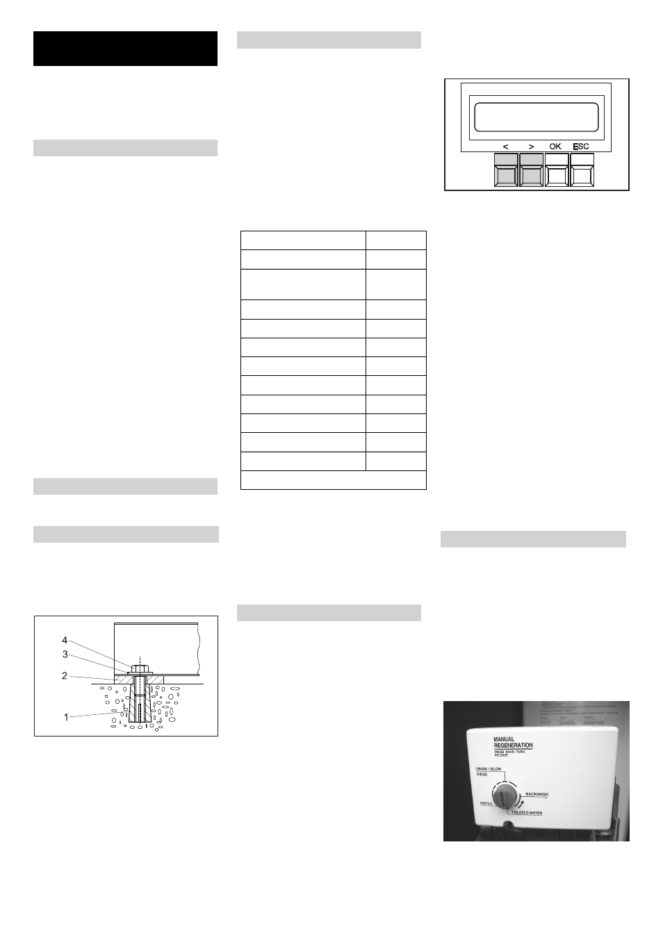
1 Dowel pin M10 (4x)
2 Unterlegplatte 5 mm (4x) Unterlegplatte
2 mm (4x)
3 Washer 10,5 (4x)
4 Hexagon screw M10 (4x)
Note
Impurities in the inlet water can damage the
unit. Kärcher recommends the use of a wa-
ter filter (see "accessories").
To ensure frost protection of the plant, the
water inlet must be protected against freez-
ing (through insulation and accompanying
heating).
ṇ
Warning
Risk of damage to the plant if water supply
is not of suitable quality. Use water only of
potable quality as water supply to the plant.
Quality requirements for tap water:
For connection values refer to technical
specifications.
Guide the inlet hose from the bottom
through the opening in the plant and
connect it to the base exchanger.
Install the solenoid valves, chemical
valve and the dosing valve in the SS
wash and connect them (see chart in
the chapter on Function).
Guide the cable of the ABS anti-frost
mechanism (hot air blower) through the
opening of the plant and connect it in
the electrical cabinet according to the
circuit plan.
Guide the enclosed cables through the
opening in the plant, secure them with
cable binders and connect them ac-
cording to the circuit plan.
Carry out the following steps in the Control
menu for releasing the ABS osmosis:
Press "OK" button for 1 seconds
Display: Data Adjust
Press „<“ key
Display: Warm Water
Press „<“ key
Display: Options
Press "OK" key
Display: Half Load: OFF/ON
Press „<“ key
Display: Osmosis: OFF
Press "OK" key
Display: Osmosis: OFF blinking
Press „<“ key
Display: Osmosis: ON blinking
Press "OK" key
Display: Osmosis: ON glows continu-
ously
Press "ESC" key twice
Display: Save Parameter?
Press "OK" key
Display: DATA SAVING....
wait for approx. 5 seconds
Press "ESC" key
Settings completed
Inser the overflow hoses of base ex-
changer and salt tank in the drainage
pipe of the building.
Fill the salt tank with water (approx. 10
cm) Do not add any salt yet!
Open the locking valve in the inlet slow-
ly and wait until the pressure tank is
filled with water.
Remove the covering lid of the control
valve.
Press the programme button and select
the function "Backwash" by turning the
button in the direction of the arrow.
Installing the unit (only for
experts)
Preparing the installation place
Unpack the equipment
Aligning the unit and installing it
Water connection
Parameter
Value
pH value
6,5...9,5
electrical conductivity
max. 1000
μS/cm
Hydrocarbons
< 0.01 mg/l
Chloride
< 250 mg/l
Calcium
< 200 mg/l
Total hardness
< 28 °dH
Iron
< 0.2 mg/l
Manganese
< 0.05 mg/l
Copper
< 0.02 mg/l
Sulphate
< 240 mg/l
Active chloride
< 0.1 mg/l
free of bad odours
Electrical connection
Release ABS Osmosis
Turning the base exchanger on
Backwash
25
EN