Karcher SB-WASH 50-10 User Manual
Page 39
-
16
–
Light at the washing area according to
the national requirements, in order to
assure safe working for the customer
when dark.
–
Power and water supply according to
the measuring sheet.
–
By operation in the winter, an isolated/
heated water supply sytem must be
guaranteed.
–
Drain water shaft and required drain
water disposal.
–
Drill fixing holes according to the meas-
ure sheet.
Unpack the plant and sent the packaging
materials for recycling.
Line up the equipment on the level area.
Fix with the material included. Use the
inclosed spacer and set up the equip-
ment horizontal.
1 Dowel pin M10 (4x)
2 Unterlegplatte 5 mm (4x) Unterlegplatte
2 mm (4x)
3 Washer 10,5 (4x)
4 Hexagon screw M10 (4x)
Place the exhaust nozzle from outside
on the roof and fasten it from inside us-
ing the enclosed screws.
Install the outside thermostat, that it is
protected from direct sun light warm
walls and air flow.
Connect the inclosed cable in the con-
trol circuit board ( refer to pwer flow
plan).
Install the swinging spacer according to
the enclosed installation instruction on
the left side of the equipment.
Lead the high pressure hose through
the sidewall of the equipment and con-
nect with the high-pressure pump.
Connect the high-pressure hose with
the blowing gun.
Connect the steel pipe brush with the
blowing gun.
Tighten all clamping nut.
remove the brief instructionfrom the in-
struction manual, and fix it inside the
door of the circuit control board.
ṇ
Warning
Observe regulations of water supplier.
According to the applicable regula-
tions, the appliance must never be
used on the drinking water supply
without a system separator. Use a
suitable system separator manufactured by
KÄRCHER; or, as an alternative, a system
separator as per EN 12729 Type BA. Water
flowing through a system separator is con-
sidered non-drinkable.
Caution
Always connect the system separator to
the water supply, never directly to the appli-
ance!
Note
Impurities in the inlet water can damage the
unit. Kärcher recommends the use of a wa-
ter filter (see "accessories").
To ensure frost protection of the plant, the
water inlet must be protected against freez-
ing (through insulation and accompanying
heating).
ṇ
Warning
Risk of damage to the plant if water supply
is not of suitable quality. Use water only of
potable quality as water supply to the plant.
Quality requirements for tap water:
For connection values refer to technical
specifications.
Insert the inlet hose from the bottom
through the plant opening and connect it.
ƽ
Danger
The mains must be connected by an expe-
rienced technician and the requirements of
the IEC 60664-1 must be fulfilled.
Remove the 4 knurled scrwes from the
roof. The screws can be loosened fast-
er when you press the roof from the top.
Push the chimney pipe upward until the
connection to the burner has been loos-
ened.
Push the roof towards the door until it
protrudes out of the casing on the oppo-
site side.
Remove the roof upward. Caution! Do
not damage the chimney
Connect the wire to the electrical switch
cabinet.
Note
After completion, check that the electrical
connection has the correct three-phase
connection.
Check the rotation direction of the high
pressure pump. With correct direction of
rotation a strong airflow can be felt out of
the exhaust opening of the burner.
ƽ
Danger
Risk of electrical voltage. Setting may only
be done by an electrician.
Determining the hardness of tap water:
–
through the public water supply works,
–
Using hardness testing set, order no.
6.768-004.
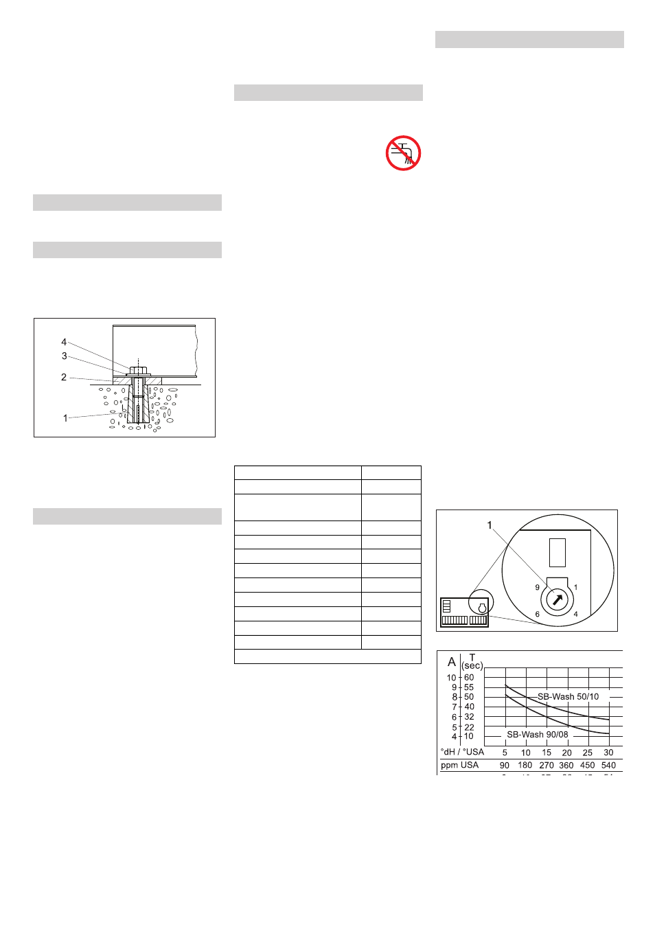
Open the switch box at the operator
panel.
1 Speed potentiometer
Locate the local water hardness in the
diagram.
Extend the vertical line upward until the
curve for the corresponding point has
been reached.
Draw a horizontal line from the intersec-
tion and read the setting value (A).
Adjust the speed potentiometer to the
value that you have ascertained (A).
Unpack the equipment
Aligning the unit and installing it
Assemble the installation parts
Exhaust nozzle
Outside anti freeze thermostat (optional)
swinging spacer (optional)
Cleaning tool
Brief instruction
Water connection
Parameter
Value
pH value
6,5...9,5
electrical conductivity
max. 2000
μS/cm
Hydrocarbons
< 0.01 mg/l
Chloride
< 250 mg/l
Calcium
< 200 mg/l
Total hardness
< 28 °dH
Iron
< 0.2 mg/l
Manganese
< 0.05 mg/l
Copper
< 0.02 mg/l
Sulphate
< 240 mg/l
Active chloride
< 0.1 mg/l
free of bad odours
Electrical connection
Adjusting the dosing of the softener liq-
uid (optional)
39
EN