Preparing your motherboard, Retention posts installation, Purging the water-block – Swiftech H20 120 R3A User Manual
Page 22: Applying thermal compound to the cpu, Fasten the water-block to motherboard
Copyright Swiftech 2004 – All rights reserved – Last revision date: 11-23-04
Rouchon Industries, Inc., dba Swiftech – 1703 E. 28
th
Street, Signal Hill, CA 90755 – Tel. 562-595-8009 – Fax 562-595-8769 - E Mail:
[email protected] – URL:
http://www.swiftnets.com
- Information subject to change without notice Page 22 of 38
1. P
REPARING YOUR
M
OTHERBOARD
Installation of the retention posts requires removal of the motherboard from the chassis.
Remove the existing heat sink
Carefully clean the CPU.
2. R
ETENTION
P
OSTS INSTALLATION
Install all the washers in the precise sequence shown in figure 1. The sequence is: Philips screw,
black fiber-washer, motherboard, black fiber-washer, lock-washer, and hex-nut. Using fiber-
washers on either side of the motherboard is critical to prevent shorting of the motherboard. Once
the posts are securely fastened to the motherboard, you can re-install it inside the chassis.
3. P
URGING THE WATER
-
BLOCK
The geometry and keep-out areas surrounding socket LGA 775 require that the MCW6000 & 6002
water-blocks be installed with the discharge spigot facing downwards. In a vertical orientation, this
prevents the water-block from purging appropriately. There are two possible strategies to purge
the water-block:
You can fill-up the circuit and purge the water-block of any air trapped inside BEFORE
fastening it to the motherboard, as shown in figure 3. TIP! If you are using a 12 volts
pump feeding from the computer power-supply, do not start-up the computer while
the cooler is not installed on the CPU
. Disconnect the power supply from the
motherboard, and use a power supply tester to start it up independently. This will allow
you to run the pump by itself, and fill-up the circuit. If you do not have a power-supply
tester
You can install the water-block onto the motherboard, but you will need to fill-up the
circuit with the computer laying flat on a table, as the water-block purges correctly when
lying horizontally.
4. C
ONNECTING THE WATER
-
BLOCK
(
S
)
TO THE COOLING CIRCUIT
Carefully identify the direction of the flow in your circuit. For the MCW6000 to operate
properly, the spigot located at the center of the water-block MUST BE USED AS THE
INLET
(see figure 1 “INLET” spigot).
Attaching the tubes:
In kit form, the MCW6000™ ships with 2’ of tube already clamped
to inlet and outlet. When sold separately, two worm-drive hose clamps are included.
Type of Coolant:
being entirely made of copper, the MCW6000™ series may be used
with pure water, and do not necessitate the use of anti-corrosion agents. The use of an
algaecide such as our HydrX™ is nonetheless highly recommended.
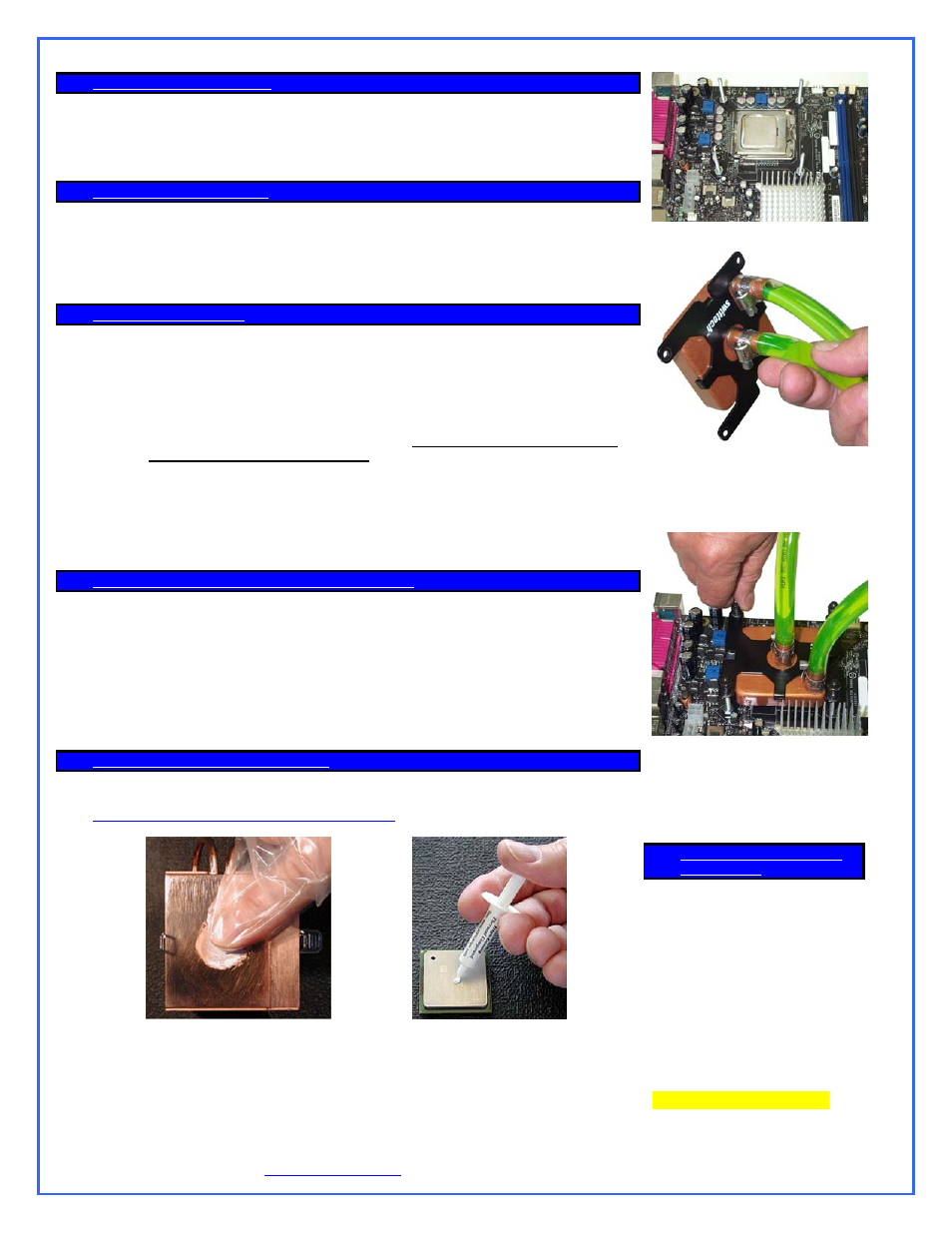
5. A
PPLYING THERMAL COMPOUND TO THE
CPU
Lightly coat the CPU with the provided Céramique™ thermal compound. Follow this link
for detailed instructions.
Rub some compound in base of water-block
first, and then clean off with lint-free cloth.
Apply small amount of compound on
the CPU heat spreader
Figure2
Install retention posts
Figure 3
Purge the air from the water-block,
by pointing the discharge spigot
upwards
Figure 4
Install water-block, hold-down plate,
and fasten the spring-nut assemblies’
in a cross pattern (finger tight).
6. F
ASTEN THE WATER
-
BLOCK TO
MOTHERBOARD
Place the water-block on the CPU
with the step side above the socket
lever. The hold-down plate is
asymmetric in order to locate the
water-block precisely inside of the
“keep out” areas. This guarantees
full compatibility of the water-block
with all LGA 775 motherboards.
Insert nylon shoulder washer and
spring on each post, and fasten the
acorn nuts in a cross pattern.
Installation is complete!