Installation instructions – Hubbardton Forge 138552 User Manual
Page 2
Installation Instructions
A92
Ondrian Pendant 13-8550 & 13-8552
Page 2 of 3
Hand-Forged,
Vermont-Made Lighting and Accessories
154 Route 30 South, Castleton, Vermont 05735
19404 Rev B
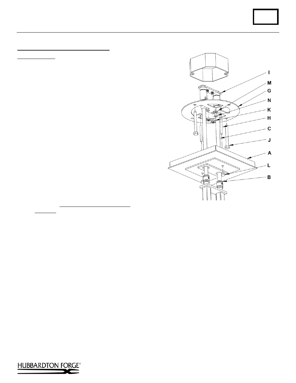
Complete Assembly & Install Fixture
(Figure 3)
Component Parts
A Canopy
B Clutch
(2)
C
Canopy Pipe (2)
G Crossbar
H Threaded Stud (2)
I Hanger
Plate
J Lag Screw (4)
K 1/4-20
Nut
(2)
L
Knurl Ball (2)
M
Cupped Washer
N
Ground Screw
Caution: This fixture must be supported independently
of an outlet box.
Caution: Be sure power is off at the main breaker box
prior to installation.
1. Using at least two lag screws (J) attach cross bar
(G) to a structural member in the ceiling, centering
the crossbar over the outlet box. We've supplied lag
screws with your fixture; however, different
materials and/or construction methods may require
different fasteners. If in doubt, contact a qualified
electrician. Do not attach crossbar directly to
outlet box.
2. Push hanger plate (I) at top of assembled fixture
up into electrical box, past the crossbar then turn the hanger plate and drop the threaded studs in the hanger plate
into the larger inner holes in the crossbar. Make sure no wires are pinched. Secure with 1/4-20 nuts (K).
3. Using suitable wire connectors (not provided), connect fixture wires to supply wires (white or ribbed side of
fixture cord to white supply, black or smooth side of fixture cord to black supply, and bare copper to bare copper
or green supply). Ground the crossbar (G) using the green ground screw (N) and cupped washer (M) to secure a
pigtail lead to the bracket. Push wires back into outlet box.
Caution: Make sure wire connectors are twisted on
securely, and no bare wire is exposed.
4. Start the threaded studs (H) into the threaded holes in the crossbar to match holes in canopy (A).
5. Slide fixture canopy up over the threaded studs (H) and against ceiling. Secure with the two knurled balls (L).
6. Refer to instructions below to install glass and diffusers.
(continued)
Figure 3