A361, Assembly & installation instructions – Hubbardton Forge 137805 User Manual
Page 3
H U B B A R D T O N F O R G E . C O M
hand-forged, vermont-made lighting and accessories
154 RT. 30 SOUTH
•
CASTLETON, VERMONT 05735
All designs and images ©1989-2014 Hubbardton Forge
®
. All rights reserved.
30714
Assembly & Installation Instructions
If you need further assistance, or find that you are missing any parts, please contact the dealer from which you purchased this product.
We hope you enjoy your fixture!
* Hubbardton Forge will not be liable for injury or damage caused by improper installation, lamping or use of this fixture.
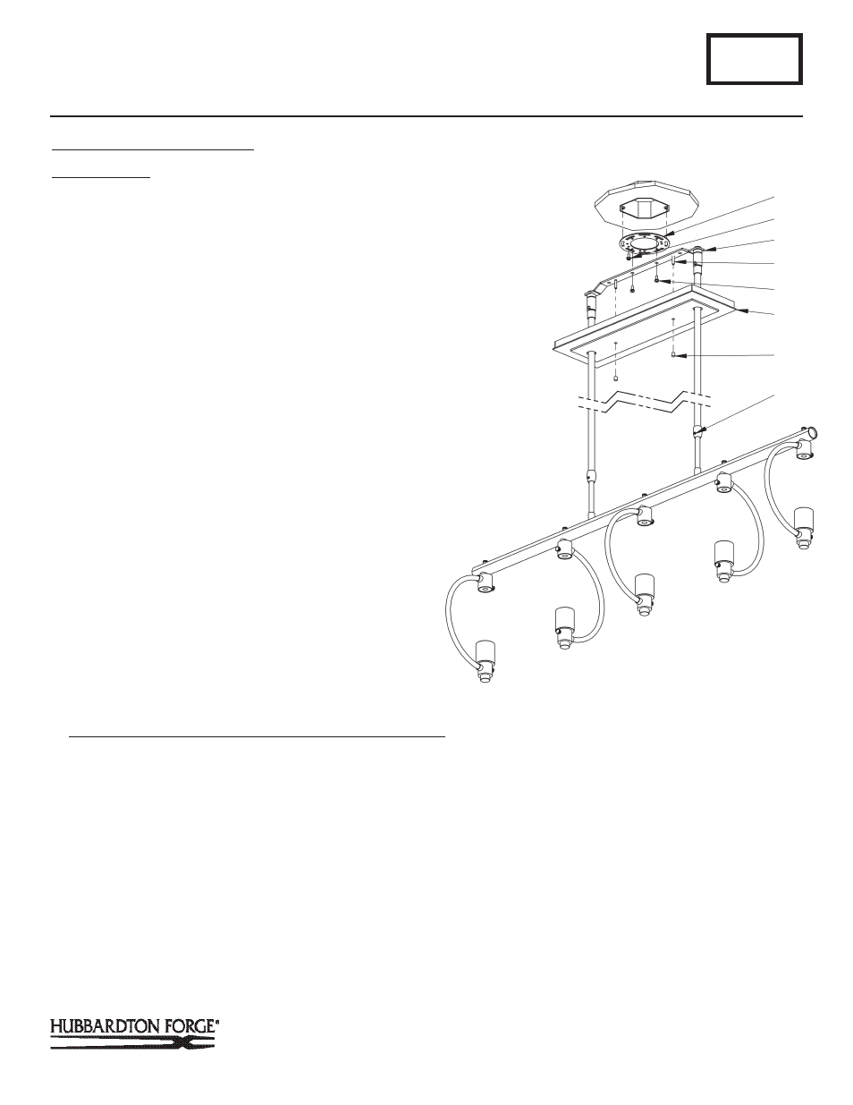
To Complete Fixture Assembly
(Figure 5)
Component Parts
E Ceiling Bracket
I Set Screw (2)
J Canopy
K Crossbar
L #8 Screw (2)
M Threaded Stud (2)
N Barrel Knob (2)
O Ground Screw
1. Using two machine screws (not provided) fasten the cross-
bar (K) to the electric box using outer oval slots to orient
fixture to desired hanging position
Note: A new electric box comes with screws. When replacing an
existing fixture, retain screws for use with the new fixture.
2. Raise fixture to ceiling. Align holes in crossbar (K) with
holes in ceiling bracket (E) and install two #8 screws (L).
3. Using suitable wire connectors (not provided) connect fix-
ture wires to supply (white to white and black to black). Run
a pigtail lead from crossbar ground screw (O) to the junction
box and connect all ground wires (bare copper or green to
bare copper or green).Push wires back into outlet box.
CAUTION: MAKE SURE WIRE CONNECTORS ARE TWISTED ON
SECURELY, AND NO BARE WIRE IS EXPOSED.
4. Raise canopy (J) to ceiling, slide over threaded studs
(M) and push firmly to ceiling, making sure that no wires
are pinched between canopy (J) and ceiling. Fasten with
barrel knob (N).
Note: Be sure both swivel notches are aligned in the same direction.
For sloped ceilings the notches should face towards the down side.
5. Once the fixture is fastened to the ceiling, tighten the set
screw (I) firmly with hex wrench provided. Only after the set
screw (I) is tight should you install the glass.
6. Refer to instructions following to install glass.
A361
Pluto 5lt Pendant 137805
Page 3 of 4
(Figure 5)
(Continued)
K
O
E
M
L
J
N
I