A311, Assembly & installation instructions – Hubbardton Forge 137665 User Manual
Page 2
If you need further assistance, or find that you are missing any parts, please contact the dealer from which you purchased this product.
We hope you enjoy your fixture!
* Hubbardton Forge will not be liable for injury or damage caused by improper installation, lamping or use of this fixture.
H U B B A R D T O N F O R G E . C O M
hand-forged, vermont-made lighting and accessories
154 RT. 30 SOUTH
•
CASTLETON, VERMONT 05735
27253 Rev D
Assembly & Installation Instructions
Complete Assembly & Install Fixture
(Figures 2 & 3)
(Continued)
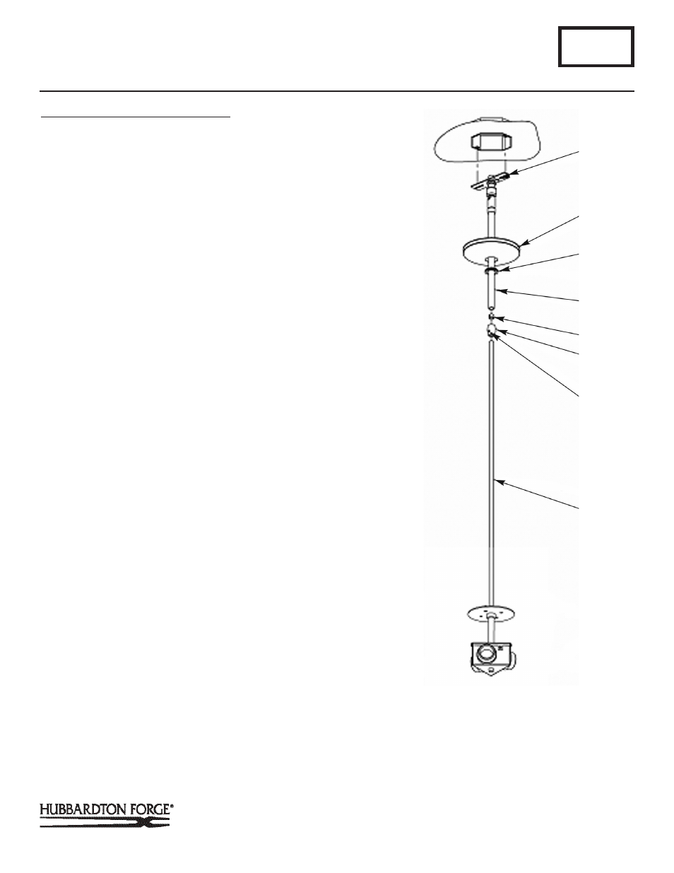
2. Thread wires from the fixture pipe (J) through the canopy
pipe (F).
3. Unscrew the clutch (H) from the canopy pipe (F); slide it
across the wires and onto the fixture pipe (J). Follow this
with the plastic clutch sleeve (G), oriented so the tapered
end of the clutch sleeve nests in the clutch (Figure 3).
4. Slide the canopy pipe (F) as far as necessary to give you
the total length of the fixture which you desire. Be care-
ful not to scratch the pipe surfaces and to pull excess wire
up through the canopy pipe (F). There must be a minimum
1-1/2" of inner pipe inside the outer pipe. Hand-tighten the
clutch to temporarily hold this adjustment. The clutch is not
securely fastened at this point; do not depend on it to hold
the fixture.
Note: To ensure full connection strength, be sure the tapered end
of the plastic clutch sleeve is oriented toward the clutch when as
sembled and securely tighten set screw (Figure 3).
5. Carefully slide canopy ring (E) and canopy (D) down over
fixture pipe (J) until they rest on the fixture.
6. Using two machine screws (not provided), fasten the cross
bar to the electric box.
Note: A new electric box comes with screws. When replacing a
fixture, retain the existing screws for use with the new fixture.
7. Using suitable wire connectors (not provided), connect fix-
ture wires to supply wires (white to white supply, black to
black supply). Run a pigtail lead from crossbar ground
screw to the junction box and connect all ground wires (bare
copper or green to bare copper or green). Push wires back
into outlet box.
CAUTION: MAKE SURE WIRE CONNECTORS ARE TWISTED ON
SECURELY, AND NO BARE WIRE IS EXPOSED.
8. Slide fixture canopy (D) against ceiling, and secure with
canopy ring (E).
9. Once the fixture is fastened to the ceiling, tighten the set
screw (I) firmly with hex wrench provided. Only after the set
screw (I) is tight should you install the glass.
A311
Brindille Adjustable Pendant 137665
Page 2 of 4
(Figure 3)
(Continued)
A
D
F
E
G
H
I
J