A274, Assembly & installation instructions – Hubbardton Forge 137630 User Manual
Page 3
Assembly & Installation Instructions
A274
For Pendant 13-7630
Page 3 of 4
Hand-Forged,
Vermont-Made Lighting and Accessories
P.O. Box 827, 154 Route 30 South, Castleton, Vermont 05735
24824 Rev A
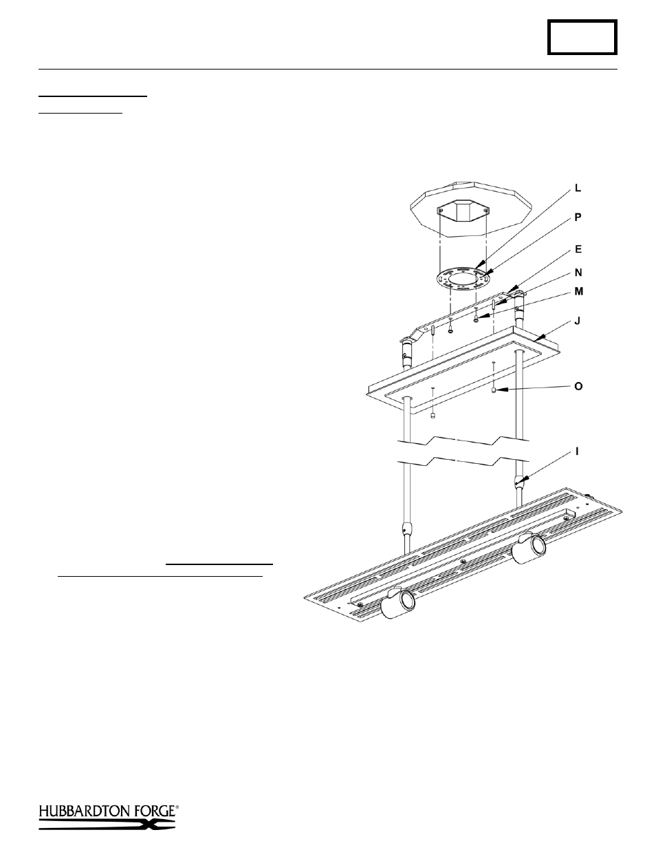
To Install to Ceiling
(Figure 5)
Component Parts
E Ceiling
Bracket
I
Set Screw (2)
J Canopy
L Crossbar
M #8 Screw (2)
N Threaded Stud (2)
O Barrel Knob (2)
P Ground
Screw
1. Thread studs (M) through appropriate holes in
crossbar (L) to match holes in canopy (J).
2. Using two machine screws (not provided)
fasten the crossbar (L) to the electric box
using outer oval slots to orient fixture to
desired hanging position.
Note: A new electric box comes with screws.
When replacing an existing fixture, retain
screws for use with the new fixture.
3. Raise fixture to ceiling aligning holes in
crossbar (L) with holes in ceiling bracket (E)
install two #8 screws (M).
4. Using suitable wire connectors (not provided)
connect fixture wires to supply (white to white
and black to black). Run a pigtail lead from
crossbar ground screw (P) to the junction box
and connect all ground wires (bare copper or
green to bare copper or green).Push wires
back into outlet box.
Caution:
Make sure wire connectors are
twisted on securely, and no bare wire is
exposed.
5. Raise canopy (J) to ceiling over threaded studs
(N) and push firmly to ceiling, making sure
that no wires are pinched between canopy and
ceiling. Fasten with barrel knob (O).
Note: Be sure both swivel notches are aligned
in the same direction. For sloped ceilings the
notches should face towards the down side.
6. Once the fixture is fastened to the ceiling,
tighten the set screw (I) firmly with hex
wrench provided. Only after the set screw (I)
is tight should you install the glass.
7. Refer instructions following to install diffuser and shade.
(continued)
(Figure 5)