A136, Assembly & installation instructions – Hubbardton Forge 137523 User Manual
Page 3
Assembly & Installation Instructions
A136
For Ellipse Pendants 13-7523 & 137523F
Page 3 of 4
Hand-Forged,
Vermont-Made Lighting and Accessories
P.O. Box 827, 154 Route 30 South, Castleton, Vermont 05735
21041 Rev B
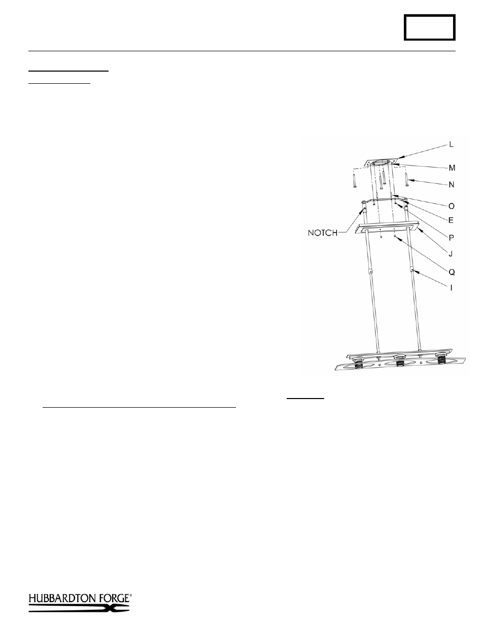
To Install to Ceiling
(Figure 5)
Component Parts
E Ceiling
Bracket
I
Set Screw (2)
J Canopy
L Crossbar
M Stud
(2)
N Lag Screw (4)
O Threaded Stud (2)
P Hex Nut (2)
Q Barrel Knob (2)
1. Thread studs (O) through appropriate holes in crossbar (L) to
match holes in canopy (J).
2.
Using two machine screws (not provided) fasten crossbar (L) to
the electric box using tab holes to orient fixture to desired hanging
position.
Note: A new electric box comes with screws. When
replacing an existing fixture, retain the screws for use with the new
fixture.
Alternate Mounting Option - Using four lag screws (N) attach
crossbar (L) to a structural member in the ceiling, centering the
crossbar over the outlet box. We've supplied lag screws with your
fixture; however, different materials and/or construction methods
may require different fasteners. If in doubt, contact a qualified
electrician.
3. Raise fixture to ceiling aligning studs in crossbar (L) with holes in
ceiling bracket (E).
4. Thread hex nut (P) onto studs (M) and tighten.
5. Using suitable wire connectors (not provided) connect fixture
wires to supply (white to white and black to black, and bare copper
to bare copper or green supply). Push wires back into outlet box.
Caution:
Make sure wire connectors are twisted on securely, and
no bare wire is exposed.
6. Raise canopy (J) to ceiling over threaded studs (O) and push firmly
to ceiling, making sure that no wires are pinched between canopy
and ceiling. Fasten with barrel knob (Q).
Note: Be sure both swivel notches are aligned in the same direction. For sloped
ceilings the notches should face towards the down side.
7. Once the fixture is fastened to the ceiling, tighten the set screw (I) firmly with hex wrench provided. Only after the
set screw (I) is tight should you install the glass.
8. Refer to instructions for installing glass.
(continued)
(Figure 5)