A246, Assembly & installation instructions – Hubbardton Forge 134505 User Manual
Page 2
Assembly & Installation Instructions
A246
For Adjustable Mobius Shade Pendant 13-4505
Page 2 of 7
Hand-Forged,
Vermont-Made Lighting and Accessories
P.O. Box 827, 154 Route 30 South, Castleton, Vermont 05735
24615
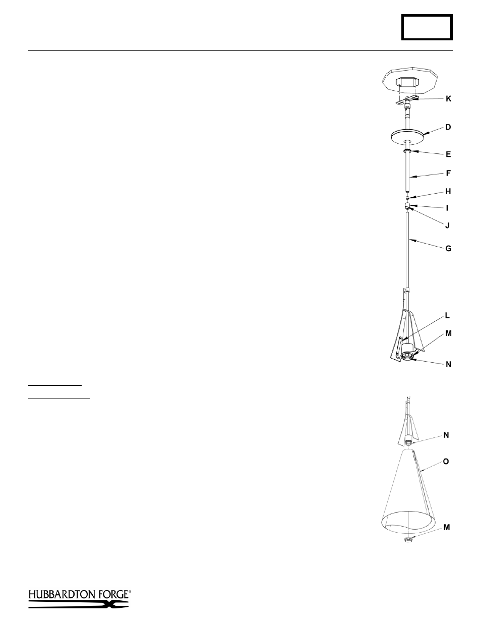
3. Unscrew the clutch (I) from the canopy pipe (F); slide it across the wires and onto the
fixture pipe (G). Follow this with the plastic clutch sleeve (H), oriented so the tapered
end of the clutch sleeve nests in the clutch (Figure 2).
4. Slide the canopy pipe (F) as far as necessary to give you the total length of the fixture
which you desire. Be careful not to scratch the pipe surfaces and to pull excess wire
up through the canopy pipe (F). There must be a minimum 1-1/2" of inner pipe inside
the outer pipe. Hand-tighten the clutch to temporarily hold this adjustment. The clutch
is not securely fastened at this point; do not depend on it to hold the fixture.
Important: To ensure full connection strength, be sure the tapered end of the plastic
clutch sleeve is oriented toward the clutch when assembled and securely tighten set
screw (Figure 3).
5. Carefully slide canopy ring (E) and canopy (D) down over fixture pipe (G) until they
rest on the fixture.
6. Using two machine screws (not provided), fasten the crossbar to the electric box.
Note: A new electric box comes with screws. When replacing a fixture, retain the
existing screws for use with the new fixture.
7. Using suitable wire connectors (not provided), connect fixture wires to supply wires
(white to white supply, black to black supply). Run a pigtail lead from crossbar
ground screw (K) to the junction box and connect all ground wires (bare copper or
green to bare copper or green). Push wires back into outlet box.
Caution: Make sure
wire connectors are twisted on securely, and no bare wire is exposed.
8. Slide fixture canopy (D) against ceiling, and secure with canopy ring (E).
9. Once the fixture is fastened to the ceiling, tighten the set screw (J) firmly with hex
wrench provided.
10. Remove retaining ring (M) from socket (N). Slip shade spider (L) from socket and
store both parts for later use. Retaining ring and shade spider are shipped installed on
socket.
11. Refer to instructions below to install shade and light bulb.
Install Shade
(Figure 4)
Component Parts
M Retaining
Ring
N Socket
O Shade
Assembly
1. Refer to instructions beginning on next page to assemble shade.
2. Slip shade assembly (O) over socket (N).
3. Thread retaining ring (M) onto socket (N).
4. Install light bulb. (not included)
5. Restore electricity at the main breaker.
(continued)
(Figure 4)
(Figure 3)