A338, Assembly & installation instructions – Hubbardton Forge 136550 User Manual
Page 2
If you need further assistance, or find that you are missing any parts, please contact the dealer from which you purchased this product.
We hope you enjoy your fixture!
* Hubbardton Forge will not be liable for injury or damage caused by improper installation, lamping or use of this fixture.
H U B B A R D T O N F O R G E . C O M
hand-forged, vermont-made lighting and accessories
154 RT. 30 SOUTH
•
CASTLETON, VERMONT 05735
All designs and images ©1989-2013 Hubbardton Forge
®
. All rights reserved.
28322 Rev A
Assembly & Installation Instructions
To Assemble Fixture
(Figures 1,2 & 3)
(Continued)
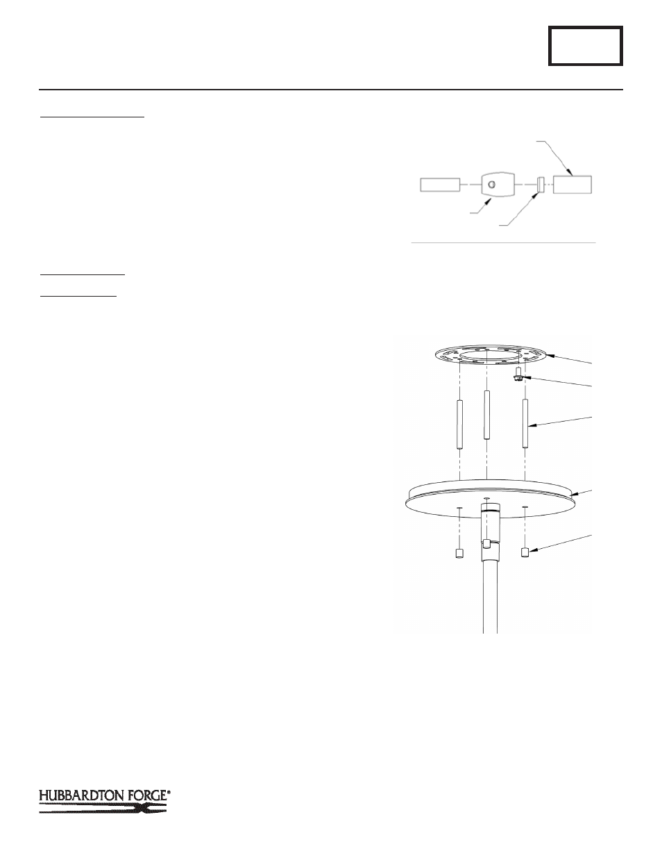
Important: To ensure full connection strength, be sure the tapered
end of the plastic clutch sleeve is oriented toward the clutch when
assembled and securely tighten set screw (Figure 3).
8. Stop. Please see installation instructions on next page.
9. Once the fixture is fastened to the ceiling, tighten the set
screw (D) firmly with hex wrench provided. Only after the set
screw (D) is tight should you install the glass.
To Install Fixture
(Figure 4)
Component Parts
A Canopy
I Crossbar
J Ground screw
K Threaded stud (3)
L Knobs (3)
CAUTION: BE SURE POWER IS OFF AT THE MAIN BREAKER BOX
PRIOR TO INSTALLATION.
1. Thread studs (K) through appropriate holes in the crossbar
(I) to match hole centers on canopy (A). Move ground screw
(J) to another available threaded hole if necessary.
2. Using two machine screws (not provided), fasten the cross-
bar (I) to the electric box using outer oval slots to orient
fixture to desired hanging position.
Note: A new electric box comes with screws. When replacing
a fixture, retain the existing screws for use with the new fixture.
3. Using suitable wire connectors (not provided) connect fix-
ture wires to supply (white to white and black to black). Run
a pigtail lead from crossbar ground screw (J) to the junction
box and connect all ground wires (bare copper or green to
bare copper or green).
CAUTION: MAKE SURE WIRE CONNECTORS ARE TWISTED ON
SECURELY, AND NO BARE WIRE IS EXPOSED.
4. Slide fixture canopy (A) with fixture attached, over threaded
studs (K) and push firmly to ceiling making sure that no
wires are pinched between fixture canopy and ceiling. Fas-
ten with the knobs (L). Be sure studs (K) are fully seated in
the knobs (L).
Note: For sloped ceilings the notch in the swivel should face
towards the down side.
A338
Moreau Three Light Pendant 136550
Page 2 of 3
K
I
(Figure 4)
J
LARGE DIAMETER PIPE
CLUTCH
PLASTIC CLUTCH SLEEVE
(Figure 3)
A
(Continued)
L