Hubbardton Forge 207673 User Manual
B257, Installation instructions
H U B B A R D T O N F O R G E . C O M
hand-forged, vermont-made lighting and accessories
154 RT. 30 SOUTH
•
CASTLETON, VERMONT 05735
All designs and images ©1989-2013 Hubbardton Forge
®
. All rights reserved.
27016 Rev A
Installation Instructions
If you need further assistance, or find that you are missing any parts, please contact the dealer from which you purchased this product.
We hope you enjoy your fixture!
* Hubbardton Forge will not be liable for injury or damage caused by improper installation, lamping or use of this fixture.
Please Note: This fixture is designed to be mounted on a standard
wall surface and may not be suitable for all applications. If installing in
a non-wood frame application, we recommend consulting a qualified
builder or electrician.
After installation extra hardware and accessories are possible; our kits
are used on multiple products and options.
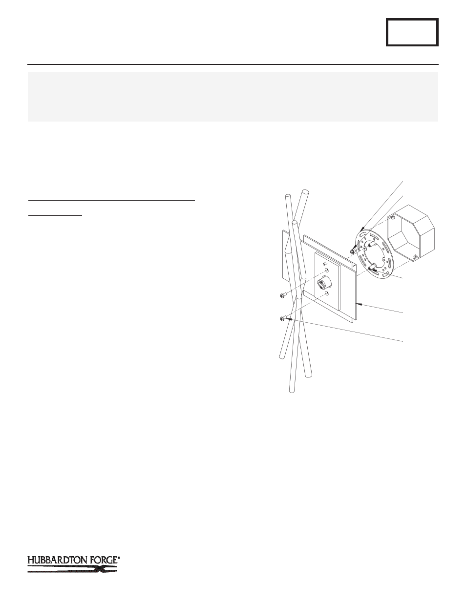
To Mount Fixture to Wall with Standard 4” Box
(Figure 1)
Component Parts
A Crossbar Assembly
B Ground Screw
C Threaded Standoff
D Fixture
E 8-32 Mounting Screw
CAUTION: BE SURE POWER IS OFF AT THE MAIN BREAKER BOX
PRIOR TO INSTALLATION.
1. Carefully unpack the fixture from the carton.
2. Using two machine screws (not provided), fasten the
crossbar (A) to the electric box making crossbar (A) is level.
Orientation of the threaded standoffs (C) is critical. (See Fig-
ure 1 for proper orientation.)Using two machine screws (not
provided), fastten the crossbar (A) to the electric box.
Note: A new electric box comes with screws. When replacing a
fixture, retain the existing screws for use with the new fixture.
3. Hold the fixture assembly (D) close to the wall and using
suitable wire connectors, not provided, connect fixture wires
to supply (white to white or ribbed and black to black or
smooth). Run a pigtail lead from crossbar ground screw (B)
to the junction box and connect all ground wires (bare cop-
per or green to bare copper or green).
CAUTION: MAKE SURE WIRE CONNECTORS ARE TWISTED ON
SECURELY, AND NO BARE WIRE IS EXPOSED.
4. Slide fixture assembly (D) over threaded standoffs (C) and
push firmly to wall, making sure that no wires are pinched
between fixture back and wall. Fasten with mounting
screws (E).
B257
Brindille Glass Sconce 207670L, 207670R, 207673L & 207673R
Page 1 of 2
CAUTION: FAILURE TO INSTALL THIS FIXTURE PROPERLY MAY RESULT IN SERIOUS PERSONAL INJURY OR DEATH AND
PROPERTY DAMAGE. We recommend installation by a licensed electrician. This product must be installed in accordance with
applicable installation code(s), by a person familiar with the construction and operation of the product and the hazards involved.*
Caution: Do not exceed maximum wattage noted on fixture. Use only recommended bulbs with fixture.
(Figure 1)
A
B
C
D
E