A345, Assembly & installation instructions – Hubbardton Forge 137675 User Manual
Page 2
If you need further assistance, or find that you are missing any parts, please contact the dealer from which you purchased this product.
We hope you enjoy your fixture!
* Hubbardton Forge will not be liable for injury or damage caused by improper installation, lamping or use of this fixture.
H U B B A R D T O N F O R G E . C O M
hand-forged, vermont-made lighting and accessories
154 RT. 30 SOUTH
•
CASTLETON, VERMONT 05735
All designs and images ©1989-2013 Hubbardton Forge
®
. All rights reserved.
30030 Rev -
Assembly & Installation Instructions
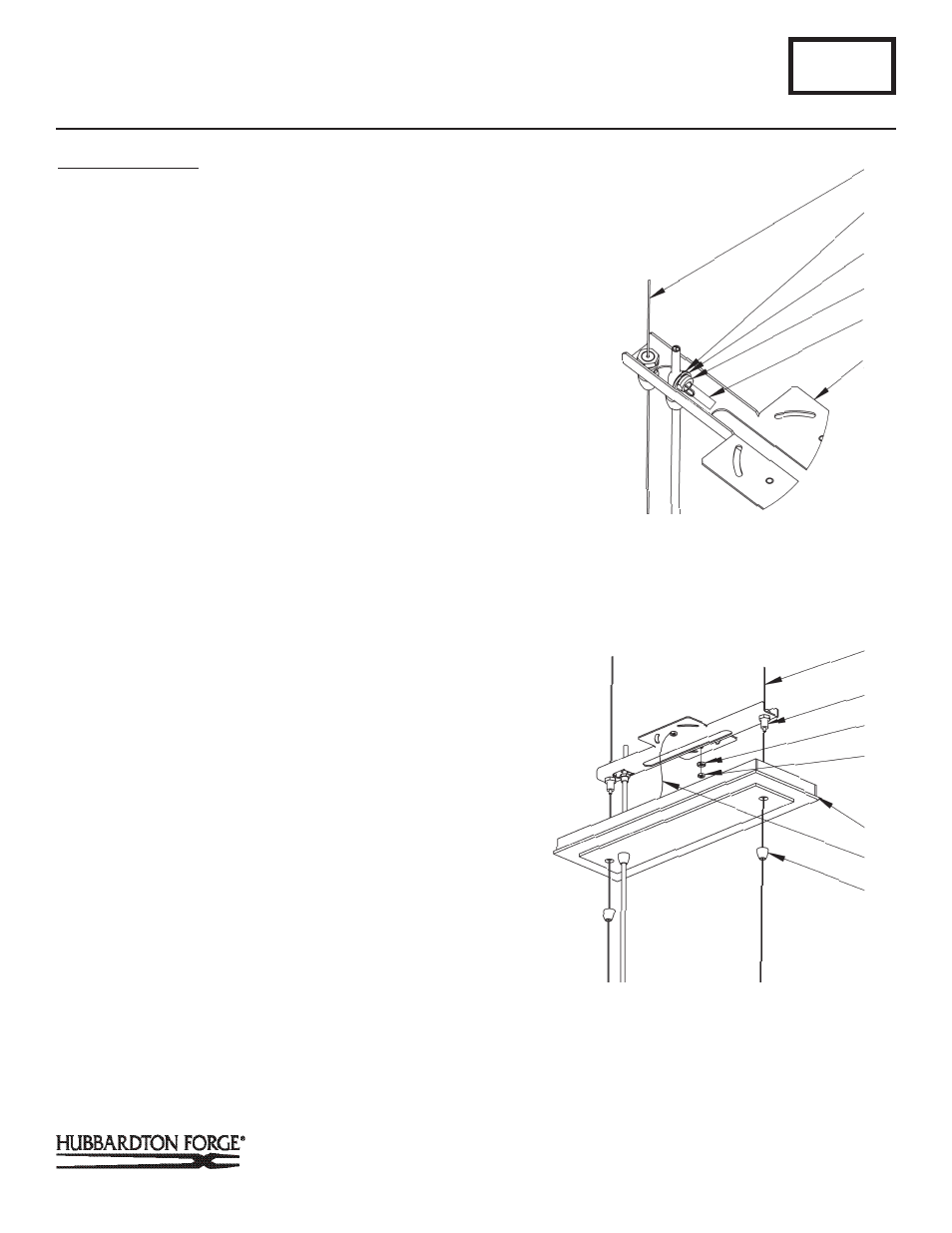
To Install to Ceiling
(Figures 2-4)
(Continued)
6. Slip gripper nuts (C) onto the support cables (E) and allow to
rest on top of fixture (F).
7. Pull support cables (E) and supply wire (G) through canopy
(D). Attach canopy support cable (L) to ceiling bracket using
hex nut (K).
8. Raise fixture (F) and push support cables (E) through cable
grippers (B) until desired fixture height is accomplished and
level.
Note: Make sure orientation of slot in the ceiling bracket matches
location of supply wire from fixture.
9. Slip supply wire (G) through strain relief (H) and push supply
wire (G) through slot on the bottom of ceiling bracket (A)
followed by washer (I). Adjust location of strain relief (H) on
supply wire (G) until it will snap into location provided on
ceiling bracket (A).
Note: Make sure orientation of slot in the ceiling bracket matches
location of supply wire from fixture.
10. Snap strain relief (H) onto supply wire (G) and push into tab
on ceiling bracket (Figure 3).
11. Once support cables are at the correct height, excess cable
can be cut off. To keep the strands of cable together a small
piece of electrical tape can be applied to the cut end.
12. Cut excess supply wire (G) allowing enough left (approx. 6”)
to make connections in the electrical box. Strip outside
jacket being careful not to cut through shielding of the two
inner conductors.
13. Run a pigtail lead from the ceiling bracket (A) using cupped
washer (J) and hex nut (K) to the junction box. Using suit
able wire connectors (not provided) connect unshielded
wire from supply wire (G) to all ground wires (bare copper or
green shielded) (Figure 4).
14. Using suitable wire connectors (not provided) connect
fixture wires to supply (wire with white tracer to white and
wire with no tracer to black).
CAUTION: MAKE SURE WIRE CONNECTORS ARE TWISTED ON
SECURELY, AND NO BARE WIRE IS EXPOSED.
A345
Oceanus Pendant 137675
Page 2 of 3
J
D
L
(Figure 3)
E
B
(Figure 4)
K
C
(Continued)
TAB
E
I
A
H
G