A365, Assembly & installation instructions – Hubbardton Forge 138650 User Manual
Page 2
If you need further assistance, or find that you are missing any parts, please contact the dealer from which you purchased this product.
We hope you enjoy your fixture!
* Hubbardton Forge will not be liable for injury or damage caused by improper installation, lamping or use of this fixture.
H U B B A R D T O N F O R G E . C O M
hand-forged, vermont-made lighting and accessories
154 RT. 30 SOUTH
•
CASTLETON, VERMONT 05735
All designs and images ©1989-2013 Hubbardton Forge
®
. All rights reserved.
30852
Assembly & Installation Instructions
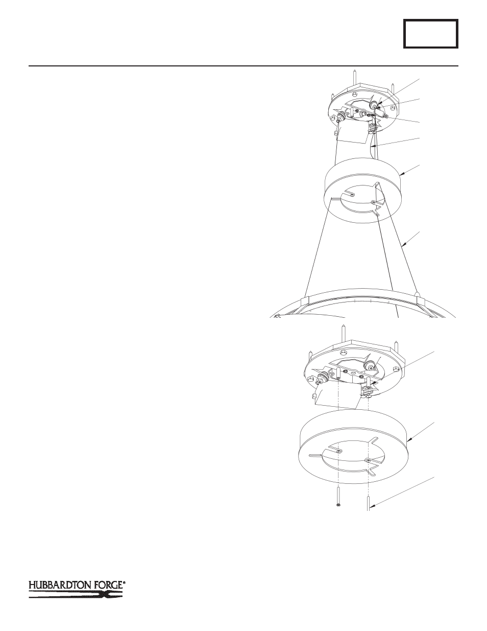
5. Loosen cable gripper locks before trying to install cables.
(Figure 3).
Note: Support cable (F) will not be able to pass through the cable
gripper (G) unless the locks are loose.
6. Raise fixture and push support cables (F) through the canopy
(C) and into the cable grippers (G) until desired fixture
height is accomplished and level. Once desired height
is accomplished and product is level, tighten
cable gripper locks. (Figure 3).
7. Using suitable wire connectors (not provided) connect driver
wires marked ‘supply’ to supply wires (white to white, black
to black). Connect all ground wires.
8. Push supply connectors up though the slot in the insulating
barrier so that connections are inside the outlet box.
CAUTION: MAKE SURE WIRE CONNECTORS ARE TWISTED ON
SECURELY, AND NO BARE WIRE IS EXPOSED.
9. Locate the 4 PVC isolation sleeves (provided). Locate
support cable (F) with a (+) label on the fixture and
slip the 2 red isolation sleeves (provided) over the end.
Locate support cable (F) with a (-) label on the fixture and
slip the two black isolation sleeve (provided) over the end.
10. Using heavy duty cable cutters, cut excess supply/support
cable (F) allowing enough left (approx.3/ 4”) to make
connections.
11. Using suitable wire connectors (provided) connect support
cable (F) with red isolation sleeve to red driver wire with (+)
label attached. Connect support cable (F) with black
isolation sleeve to black driver wire with (-) label attached.
CAUTION: MAKE SURE WIRE CONNECTORS ARE ON SECURELY, AND
NO BARE WIRE IS EXPOSED.
12. Remove canopy support cable (D) by removing #8 screw
(E) from ceiling bracket (A) and #8 nut from canopy
(C) (discard cable).
13. Raise the canopy (C) and attach to ceiling bracket (A) with
two flat head screws (H) (Figure 4).
14. Slip canopy cover (J) onto canopy nipple (I) (Figure 5, next
page).
15. Thread cap (K) on to canopy nipple (I). Tighten against
canopy cover (J) until snug.
16. Refer to instructions following to assemble and install shade.
A365
Bento LED Pendant 138650D
Page 2 of 6
(Figure 3)
(Continued)
(Figure 4)
A
C
H
G
GRIPPER
LOCK
D
C
F
(Continued)
E