Wiring and powering on a dc powered system – Allied Telesis AT-LX3800U User Manual
Page 63
AT-LX3800U Multi-Service Transport System Installation and Maintenance Guide
63
Wiring and Powering On a DC Powered System
For a DC powered system, perform the following steps:
1. Before you attach wires to the DC terminal block on the DC power
supply, review the following warning:
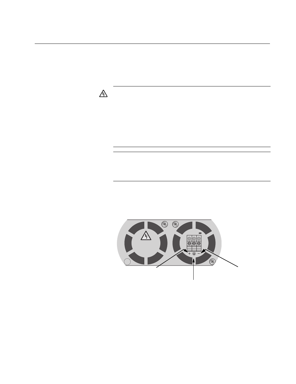
2. On the rear side of the DC power supply is a DC terminal block.
Starting from the left side of the terminal block, identify the positive,
frame ground, and negative terminals using the diagram adjacent to
the terminal block as shown in Figure 40.
Figure 40. Positive, Frame Ground, and Negative Terminals
Warning: As a safety precaution, install a circuit breaker with a
minimum value of 15 Amps between the equipment and the DC
power source.
Always connect the wires to the LAN equipment first before you
connect the wires to the circuit breaker. Do not work with HOT
feeds to avoid the danger of physical injury from electrical
shock. Always be sure that the circuit breaker is in the OFF
position before connecting the wires to the breaker.
11
A tray cable is required to connect the power source if the unit
is powered by centralized DC power. The tray cable must be a
UL listed Type TC tray cable and rated at 600 V and 90
degrees C, with three conductors, minimum 14 AWG.
26
703
LXPWR/DC
FOR CENTRALIZED DC
POWER CONNECTION,
INSTALL ONLY IN A
RESTRICTED ACCESS
LOCATION
40-60VDC
Positive
Frame Ground
Negative