Figure 39. on/off switch in on position – Allied Telesis AT-LX3800U User Manual
Page 62
Chapter 2: Installation
62
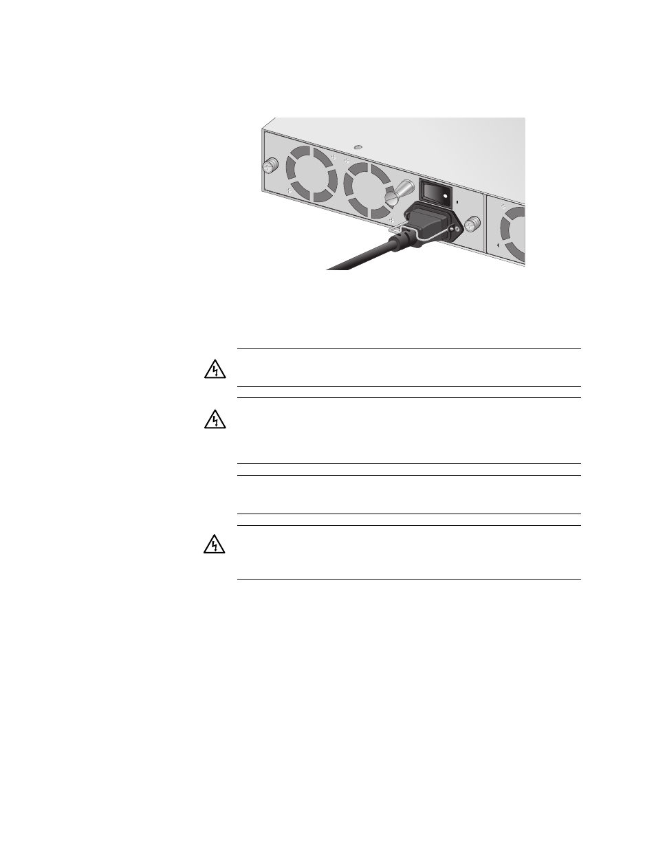
6. Move the On/Off power switch to the On position, as shown in
Figure 39. On/Off Switch in On Position
7. When power is applied, the chassis begins to load the AT-S65
software.
The chassis is now ready for network operations.
No further installation steps are required if you do not need to change the
default parameter settings of the chassis, which are listed in the AT-S65
Management Software User’s Guide. However, if you want to manage the
chassis or review the settings, refer to “Starting a Local Management
Session” on page 66 and “Starting a Remote Management Session” on
page 68.
Warning: Power cord is used as a disconnection device. To de-
energize equipment, disconnect the power cord.
5
Class I Equipment. This equipment must be earthed. The power
plug must be connected to a properly wired earth ground socket
outlet. An improperly wired socket outlet could place hazardous
voltages on accessible metal parts.
6
Pluggable Equipment. The socket outlet shall be installed near
the equipment and shall be easily accessible.
7
Warning: This unit might have more than one power cord. To
reduce the risk of electric shock, disconnect all power cords
before servicing the unit.
32
PWR A
AT-LXPWRA
C
100-240V
AC
~
ON